Sub Station 16-R Installation & Operation Manual V2.1 Cloud Electronics Limited 140 Staniforth Road, Sheffield, S9 3HF England Tel +44 (0) 114 244 7051 Fax +44 (0) 114 242 5462 E-mail info@cloud.co.uk Web site http://www.cloud.co.
Sub Station 16-R: Installation and operation manual 1 Sub Station 16-R Installation and operation manual Contents Section 16-07-02 V2.1 Page 1 Safety Notes...............................................................................2 2 General ......................................................................................2 3 The RJ45 Connection ................................................................2 4 Schematic Diagram...........................................................
2 1 Sub Station 16-R: Installation and operation manual Safety Notes • • • • • • • 2 Do not expose this unit to water or moisture Do not expose the unit to naked flames. Do not block or restrict any air vent Do not operate the unit in ambient temperatures above 35oC There are no internal user adjustable parts. Do not remove covers. Refer any servicing to qualified service personnel. Do not replace the power transformer with any other type For more detailed information refer to the rear of the manual.
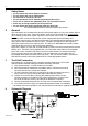
Sub Station 16-R: Installation and operation manual 5 3 Installation The Cloud Sub Station 16-R is suitable for mounting in a standard 19” equipment rack where it will occupy two units of rack space. The Sub Station 16-R is 170mm deep, but a depth of 235mm should be allowed to clear the rear panel connectors. When possible, avoid positioning the unit in close proximity to magnetic fields or equipment operating at a high temperature.
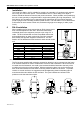
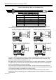
4 Sub Station 16-R: Installation and operation manual When mounted to framework the RH-8 should be positioned at 45o (see left hand diagram below), Ideally the RH-8 should also be positioned to one side of the user instead of directly in front (See right hand diagram below) When mounted directly on to a wall or perhaps the bulkhead of an exercise machine, it may be preferable to hard wire a cable directly to the RH-8 using its internal screw terminals, a diagram and wiring information for this are shown
Sub Station 16-R: Installation and operation manual 5 Cable for Hard Wiring a WP-8 to a Sub Station 16-R Cable Information for Wiring the WP-8 WP-8 (IDC) Sub Station 16-R (RJ45) CAT 5* Pin 1 Pin 8 Brown/White Pin 2 Pin 7 White/Brown Pin 3 Pin 6 Green/White Pin 4 Pin 5 White/Blue Pin 5 Pin 4 Blue/White Pin 6 Pin 3 White/Green Pin 7 Pin 2 Orange/White Pin 8 Pin 1 White/Orange *The CAT 5 colour is described as the dominant colour first with the tracer second.
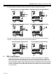
6 Sub Station 16-R: Installation and operation manual It is also possible to obtain a line level output from the WP-8 by wiring it as follows: Permanent Line Level Output (Stereo) Switchable Line Level Output (Stereo) Permanent Line Level Output (mono) Switchable Line Level Output (mono) The output of the WP-8 can be used to drive a pair of powered speakers if extra volume is required. The diagram below shows how this can be achieved.
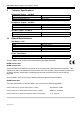
Sub Station 16-R: Installation and operation manual 9 7 Technical Specifications Headphone Output – via RH-8 Nominal output level Optimum load impedance Recommended headphones 100mW rms per channel with 32Ω load 32Ω Cloud CP32 Headphone Output – via WP-8 Nominal output level Optimum load impedance Recommended headphones 100mW rms per channel with 32Ω load 32Ω Cloud CP32 Speaker Output – via WP-8 Nominal output level Optimum load impedance 10 150mW rms per channel with 8Ω load >8Ω General Specifica
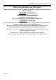
8 Sub Station 16-R: Installation and operation manual Safety Considerations and Information When the mains switch is in the off ‘O’ position the Sub Station 16-R is disconnected from the power transformer CAUTION – Installation Do not expose the unit to water or moisture Do not expose the unit to naked flames. Do not block or restrict any air vent Do not operate the unit in ambient temperatures above 35oC CAUTION – Servicing The unit contains no user serviceable parts.