
Installation Sheet
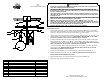
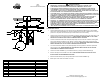
Table Of Contents

EIKO
334-03
INSTALLATION INSTRUCTIONS
WARNING/CAUTION
· DISCONNECT POWER BEFORE RE-LAMPING OR WIRING THE FIXTURE. READ ALL INSTRUCTIONS
COMPLETELY BEFORE STARTING INSTALLATION.
· TO AVOID THE RISK OF FIRE OR SHOCK, FIXTURE MUST BE INSTALLED IN COMPLIANCE WITH ALL
APPLICABLE NATIONAL AND LOCAL ELECTRICAL/BUILDING CODES. THE INSTALLATION AND
MAINTENANCE OF THIS UNIT SHOULD BE COMPLETED BY A LICENSED ELECTRICIAN OR CERTIFIED
FACTORY TRAINED TECHNICIAN.
· CALIFORNIA PROP 65: THIS LIGHTING FIXTURE CONTAINS CHEMICALS KNOWN TO THE STATE OF
CALIFORNIA TO CAUSE CANCER, BIRTH DEFECTS, AND/OR OTHER REPRODUCTIVE HARM. WASH
HANDS AFTER USE.
· REMOVE THE FIXTURE, PARTS AND PARTS BAG(S) FROM THE CARTON. BEFORE DISCARDING THE
CARTON, DOUBLE CHECK TO MAKE CERTAIN THAT ALL PARTS ARE FOUND. INSPECT THE FIXTURE
PRIOR TO INSTALLATION FOR ANY DAMAGE TO THE FIXTURE.
· DIMMING: THE FIXTURE CAN BE CONTROLLED BY A WALL DIMMING DEVICE. ONLY USE
TRIAC/ELECTRONIC DIMMER. MAKE SURE THE CARTON IS MARKED FOR USE WITH LED COMPACT
FLUORESCENT-INCANDESCENT LIGHT SOURCE ONLY. THESE CAN BE PROVIDED BY YOUR LOCAL
ELECTRICAL DISTRIBUTOR, HOME CENTER, OR HARDWARE STORE.
· PLEASE CLEAN WITH A SOFT, DRY CLOTH ONLY! DO NOT USE CLEANSERS
www.hvlgroup.com
Questions? We're here to help!
Contact us at CustomerService@hvlgroup.com
FIXTURE INSTALLATION
1. Attach the MOUNTING PAN(1) to the junction box using the MOUNTING SCREWS (2) & to the embedded
TOX(3) on the ceiling with SCREWS (4). This fixture is designed to be mounted on standard round or octagon
junction box. The junction box must be securely mounted to the structure of the building.
2. Attach the Ground wire (Green) to the ground inside the outlet box (Generally green or bare copper wire) or the
GROUND SCREW (5) on the MOUNTING PAN (1). NEVER CONNECT GROUND WIRE TO "HOT" WIRE!
FAILURE TO FOLLOW THIS COULD RESULT IN SERIOUS INJURY OR DEATH!
3. Connect the white fixture lead to the neutral (Generally white) wire in the outlet box. Fasten the wires together
with an approved fastener (WIRE NUT) (6). Starting 1" below the fastener, tightly wrap the connection with
electrical tape so that the connections seals the end of the fastener. MAKE SURE THERE ARE NO EXPOSED
WIRE OF STRANDS THAT COULD CAUSE A DANGEROUS SHORT CIRCUIT!
4. Connect the black fixture leads to the hot (Generally black) wire in the junction box. Fasten the joined wires
same as previous step. NEVER REVERSE HOT AND NEUTRAL WIRES. FAILURE TO FOLLOW THIS
COULD RESULT IN SERIOUS INJURY OR DEATH!
5. Attach the FIXTURE ASSEMBLY (7) to the MOUNTING PAN (1) using FLATHEAD SCREWS (8).
6. Screw the BULB (9) into the SOCKET of the fixture.THIS FIXTURE IS RATED FOR 60 WATTS TYPE A.
DO NOT EXCEED THE RECOMMENDED WATTAGE!
7. Install the GLASS with fitter (10) to the exposed threads on the FIXTURE ASSEMBLY (5).
8. Restore power to the outlet at the breaker or fuse box.
R
1
3
4
7
6
9
2
8
5
10
ITEM DESCRIPTION
PART NUMBER
1
MOUNTING PAN
MPT-334-03
2
MOUNTING SCREW HDW-334-03
3
TOX
HDW-334-03
4
SCREW
HDW-334-03
5
GROUND SCREW
HDW-334-03
6
WIRE NUT HDW-334-03
7
FIXTURE ASSEMBLY FAS-334-03
8
FLATHEAD SCREW
HDW-334-03
9
BULB
NOT INCLUDED
10
GLASS WITH FITTER GLS-334-03