
User guide


Command Inputs CME 2 User Guide
76 Copley Controls
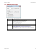
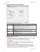
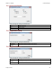
7.3: Digital Position Input Settings
View or change the settings described below.
Parameter
Description
Control Input
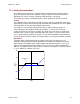
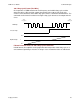
Pulse and Direction: One input takes a series of pulses as motion step commands,
and another input takes a high or low signal as a direction command.
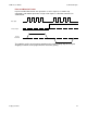
Pulse Up / Pulse Down: One input takes each pulse as a positive step command,
and another takes each pulse as a negative step command.
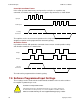
Quadrature: A/B quadrature commands from a master encoder (via two inputs)
provide velocity and direction commands.
Increment position
on
Rising Edge: Increment position on the rising edge of the input pulse.
Falling Edge: Increment position on the falling edge of the input pulse.
Stepping
Resolution
Input Pulses: Number of Input Pulses required to produce output counts.
Range: 1 to 32,767. Default: 1.
Output Counts: Number of Output Counts per given number of input pulses.
Range: 1 to 32,767. Default: 1.
Invert Command
When selected, inverts commanded direction.
For more information, see Digital Position Input Notes (p. 76).
7.3.1: Digital Position Input Notes
Three Formats
In position mode, the amplifier can accept position commands using one of these signal
formats: pulse and direction, count up/count down, and quadrature.
In all three formats, the amplifier can be configured to invert the command.
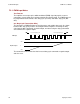
Pulse Smoothing
In digital position mode, the amplifier’s trajectory generator can be used to create
trapezoidal profiles, with programmed acceleration, deceleration and velocity, from a
simple pulse train or burst of pulses
To bypass the trajectory generator while in digital or analog position modes, set the
maximum acceleration to zero. The only limits in effect will now be the velocity loop
velocity limit and the current limits. (Note that leaving the maximum acceleration set to
zero will prevent other position modes from operating correctly.)