
User guide

Digital Inputs and Outputs CME 2 User Guide
56 Copley Controls
6.1: Digital Inputs
6.1.1: Digital Inputs Screen Overview
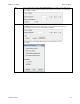
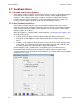
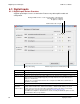
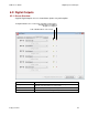
A typical Input/Output screen is shown below. Features vary with amplifier model and
configuration.
Red light: inhibited motion or active input depending on input function.
Grey light: motion not inhibited.
No light: not configured.
Lo/Hi: indicated state of input.
Hold position setting. Indicates input is used as a CAN address bit.
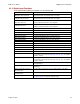
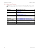
Parameter
Description
Pull up +5 V
Pulls up the group of inputs up to internal +5 V.
Pull down
Pulls the group of inputs down to internal signal ground.
Debounce Time
Specifies how long an input must remain stable at a new state before the amplifier recognizes the
state. Increase to prevent multiple triggering caused by switch bounce upon switch closures.
Range: 0 to 10,000 mSec.
Debounce does not affect inputs that have been configured as PWM, Pulse and Direction, or
Quadrature control inputs.
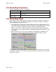
IN1- IN12
Select the function for the input. See Digital Input Functions (p. 57) for input function descriptions.
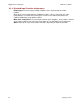
*Hold position
when limit
switch is active
Available in position mode when one or more inputs are configured as a limit switch (NEG Limit-HI
Inhibits, NEG Limit-LO Inhibits, POS Limit-HI Inhibits, or POS Limit-LO Inhibits). The *Hold
position option prevents any motion while a limit switch is active. This option uses the Abort
Deceleration rate to stop the motor as described in Trajectory Limits (p. 131).
CAUTION: If the amplifier is switched back to current or velocity mode with this option selected,
the limit switches will no longer function.
Restore Defaults restores all inputs and outputs to factory defaults. Close button closes the screen.