
User guide

CME 2 User Guide Motor/Feedback
Copley Controls 53
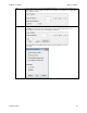
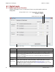
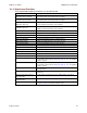
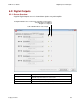
5.8: Brake/Stop Parameters
Enter the following parameters as appropriate.
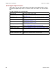
Parameter
Description
Brake/Stop Delay Time
Range of accepted values: 0 to 10,000 mSec
Brake Activation Velocity
Range of accepted values: 0 to encoder resolution dependent limit rpm (mm/s
for linear motor)
PWM Delay Brake/Stop
Response Time
Range of accepted values: 0 to 10,000 mSec
5.9: Brake/Stop Notes
Many control systems employ a brake to hold the axis when the amplifier is disabled. On
brake-equipped systems, disabling the amplifier by a hardware or software command
starts the following sequence of events.
The motor begins to decelerate (at Abort Deceleration rate in position mode or Fast
Stop Ramp rate in velocity mode). At the same time, the Brake/Stop Delay Time count
begins. This allows the amplifier to slow the motor before applying the brake.
When the motor slows to Brake/Stop Activation Velocity OR the Brake/Stop Delay
Time expires, the brake output activates and PWM Delay Brake/Stop Response Time
count begins.
When response time has passed, the amplifier’s output stages are disabled. This
delay ensures the brake has time to lock in before disabling the power section.
This sequence is not available in the current mode of operation. Instead, in current mode,
the amplifier output turns off and the brake output activates immediately when the disable
command is received.