
User guide


Homing Methods CME 2 User Guide
198 Copley Controls
E.1: Homing Methods Overview
There are several homing methods. Each method establishes the:
Home reference (limit or home switch transition or encoder index pulse)
Direction of motion and, where appropriate, the relationship of the index pulse to limit
or home switches.
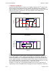
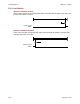
E.2: Legend to Homing Method Descriptions
As highlighted in the example below, each homing method diagram shows the starting
position on a mechanical stage. The arrow line indicates direction of motion, and the
circled H indicates the home position. Solid line stems on the index pulse line indicate
index pulse locations. Longer dashed lines overlay these stems as a visual aid. Finally,
the relevant limit switch is represented, showing the active and inactive zones and
transition.
Index Pulse
H
Positive Limit
Switch
H
Starting position
Axis
Sw itch inactive Sw itch active
Sw itch transition
Index pulse location
Direction of motion
Mechanical Stage Limits
Home position
Starting position
Note that in the homing method descriptions, negative motion is leftward and positive
motion is rightward.