
User guide


CME 2 User Guide Control Loops
Copley Controls 123
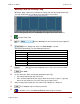
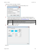
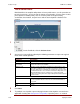
11.5.4: Diagram: Effects of Limits on Velocity Command
The following diagram illustrates the effects of the velocity loop limits.
Commanded Velocity
Limited Velocity
Vel Limit
Accel Limit Decel Limit
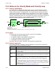
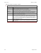
11.5.5: Velocity Loop Gains
The velocity loop uses these gains:
Gain
Description
Vp -
Velocity loop
proportional
The velocity error (the difference between the actual and the limited commanded velocity) is
multiplied by this gain. The primary effect of this gain is to increase bandwidth (or decrease
the step-response time) as the gain is increased.
Vi -
Velocity loop
integral
The integral of the velocity error is multiplied by this value. Integral gain reduces the velocity
error to zero over time. It controls the DC accuracy of the loop, or the flatness of the top of a
square wave signal. The error integral is the accumulated sum of the velocity error value
over time.
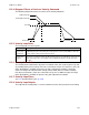
11.5.6: Velocity Gains Shift
The Velocity Gains Shift feature adjusts the resolution of the units used to express Vp and
Vi, providing more precise tuning. If the non-scaled value of Vp or Vi is 64 or less, the Low
Gains Shift option is available to increase the gains adjustment resolution. (Such low
values are likely to be called for when tuning a linear motor with an encoder resolution
finer than a micrometer.) If the non-scaled value of Vp or Vi is 24001 or higher, the High
Gains Shift option is available to decrease the gains adjustment resolution.
11.5.7: Velocity Loop Filters
See C.3: Standard Filter Types (p. 184).
11.5.8: Velocity Loop Outputs
The output of the velocity loop is a current command used as the input to the current loop.