
User guide

CME 2 User Guide Introduction
Copley Controls 11
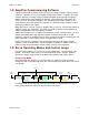
1.2: Amplifier Commissioning Software
Copley Controls CME 2 software allows fast and easy commissioning of Copley Controls
amplifiers. It provides access to all amplifier configuration controls. It supports all Copley
Controls amplifiers, including Copley’s CANopen amplifier lines and stepper amplifiers.
CME 2 communicates with amplifiers via RS-232, CAN or EtherCAT connections. On
Xenus, Accelnet, and Stepnet amplifiers, the multi-drop feature allows CME 2 to use a
single RS-232 serial connection to one amplifier as a gateway to other amplifiers linked
together by CAN bus connections.
Motor data can be saved as .ccm files. Amplifier data is saved as .ccx files that contain all
amplifier settings plus motor data. This makes it possible to quickly set up amplifiers by
copying configurations from one amplifier to another.
CME 2 also provides access to Copley Virtual Machine (CVM), a program that is set up in
CME 2 and downloaded to the amplifier to provide on-board control. When a CVM
program is running, the amplifier receives its input commands from the CVM program. For
more information, see the Copley Indexer 2 Program User’s Guide.
NOTE: The feature descriptions in this manual may not apply to all Copley Controls
amplifiers under all configurations. Significant differences between amplifier models are
noted. See the relevant hardware manual or data sheet for more information.
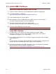
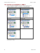
1.3: Servo Operating Modes and Control Loops
Copley Controls amplifiers use up to three nested control loops - current, velocity, and
position - to control a motor in three associated operating modes. (Stepper amplifiers
operated in stepper mode function as traditional open position loop stepper drives.)
Control Loops Model
In position mode, the amplifier uses all three loops. As shown in the typical system
illustrated below, the position loop drives the nested velocity loop, which drives the nested
current loop.
Target
Position
Position
Command
Actual CurrentDerived VelocityActual Position
Velocity
Command
Current
Command
Limited
Velocity
Limited
Current
PWM
Command
Trajectory
Generator
Position
Loop
Velocity
Limiter
Current
Limiter
Current
Loop
Motor/
Sensors
Limits
Velocity
Loop
FILTER
FILTER
In velocity mode, the velocity loop drives the current loop. In current mode, the current
loop is driven directly by external or internal current commands.