
User guide

Xenus Plus User Guide Wiring
Copley Controls 99
4.9: Control I/O
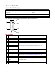
4.9.1: XEL/XPL/XML (J8)
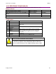
Mating Connectors
Description
Manufacturer PN
Wire Size
26 Position, 0.1 x 0.09 High Density D-Sub Female, Solder Style
Connector
Norcomp 180-026-
203L001
24 - 30 AWG
Back shell
Norcomp 979-015-
020R121
Solder style connector included in Connector Kits XEL-CK, XML-CK, and XPL-CK.
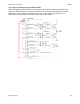
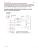
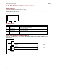
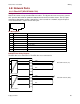
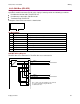
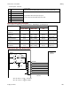
Pin connections for the bulkhead connector on the drive are shown here:
Pin Description
Pin
Signal
Function
1
Frame Ground
Cable shield connection.
2
Ref + (AIN1 +)
Analog command positive input—single analog.
3
Ref – (AIN1 -)
Analog command negative input--single analog.
4
IN1
Enable
5
IN2
Programmable input.
6
IN3
Mode-dependent. See Mode-Dependent Dedicated Inputs (p. 100).
7
IN4
8
IN5
9
AOUT
Programmable, 12-bit, ±5 Vdc.
10
IN6
Mode-dependent. See Mode-Dependent Dedicated Inputs (p. 100).
11
AIN2 +
Analog input 2 positive input.
12
AIN2 -
Analog input 2 negative input.
13
Multi-mode port /S2
Mode-dependent. See Mode-Dependent Dedicated Inputs (p. 100).
14
Multi-mode port S2
15
Signal Ground
Signal ground reference for inputs and outputs.
16
OUT1
Programmable outputs.
17
OUT2
18
OUT3 (HS)
19
Signal Ground
Signal ground for +5Vdc, inputs and outputs.
Continued…
9
1
18
26
19
10