
User guide

Xenus Plus User Guide Wiring
Copley Controls 90
4.5.2: XE2/XP2/800-1782/800-1808 (J5)
The following information is for XE2/XP2/800-1782/800-1808 drives only.
Mating Connector
Description
Euro-style 5.0 mm pluggable female terminal block.
Manufacturer PN
Wago: 721-105/026-047 (Note 1)
Wire Size
28 - 14 AWG
Recommended Wire
18 AWG
Wire Insertion/Extraction Tool
Wago: 231-131
Standard connector and tool are included in Connector Kits XEL-CK, XML-CK, and XPL-CK.
Note 1: For RoHS compliance, append “/RN01-0000” to the part numbers listed above.
Pin Description
Pin
Signal
Function
1
RTN
+24 Vdc return from battery.
2
Brake B
Return or low side of motor brake B.
3
Brake A
Return or low side of motor brake A.
4
Brake+24 Vdc
+24 Vdc for both brakes.
5
24 Vdc input
+24 Vdc Logic power supply from battery.
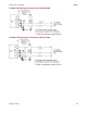
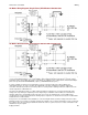
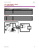
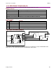
Logic Supply / Brake Wiring Diagram
Note that the +24Vdc supply must be a SELV or PELV type in applications using the XE2/XP2/800-1808
STO feature. See the Xenus Plus Dual-Axis STO Manual for further details.
Drive J5
Isolated Logic
Pow er Supply
for Brake A
J5-5
J5-4
+24 V
BRK-A
RTN
Brake A
J5-3
J5-2
J5-1
BRK +24 Vdc
BRK-B
Isolated Logic
Pow er Supply
for Brake B
Brake B
+24 Vdc
Power
Supply
(Required)