
User guide

Xenus Plus User Guide Wiring
Copley Controls 81
4.1.2: Grounding Considerations
Primary Grounding Functions
A grounding system has three primary functions: electrical safety, voltage-reference, and shielding.
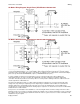
J1-3 Protective Earth Ground
The protective earth (PE) ground at J1-3 (for both single and dual axis drives), is the electrical
safety ground and is intended to carry the fault currents from the mains in the case of an internal
failure or short-circuit of electronic components. This ground is connected to the drive chassis.
Wiring to this ground should be done using the same gauge wire as that used for the mains. This
wire is a “protective bonding” conductor that should be connected to an earthed ground point and
must not pass through any circuit interrupting devices.
The pin on the drive at J1-3 is longer than the other pins on J1, giving it a first-make, last-break
action so that the drive chassis is never ungrounded when the mains power is connected.
J2 Regen and J3 Motor Connector Grounds
On Xenus Plus Single Axis drives, the ground terminals at J2-1 and J3-5 connect to the drive
chassis.
On Xenus Plus Dual Axis drives, the ground terminals at J2-3 and J3/J4-1 connect to the drive
chassis.
These ground terminals are provided as cable shield and protective earth connection points for the
motor and regen resistor cables. Connection of cable shields to these points is made to provide
electrical noise reduction. Connection of motor or regen cable protective earth conductors to these
points is made to prevent the motor or regen resistor housing from becoming hazardous live in the
event of an insulation failure. Protective earth connections for the motor and regen resistor
housings are subject to local electrical codes and must be reviewed for compliance with those
codes. It is the responsibility of the end user to ensure compliance with local electrical codes and
any other applicable standards. It is strongly recommended that motor and regen resistor housings
also be connected to protective earth connection points located as close to the motor and regen
resistor as possible. In many applications, the machine frame is used as a primary or supplemental
protective earth connection point for the motor and regen resistor housings.
Signal Grounding
The drive signal ground must be connected to the control system signal ground. The drive signal
ground is not connected to earth ground internal to the drive. Therefore, the control system signal
ground can be connected to earth ground without introducing a ground loop.
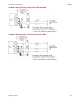
Cable Shielding
Shields on cables reduce emissions from the drive and help protect internal circuits from
interference due to external sources of electrical noise. The shields shown in the wiring diagrams
are also required for CE compliance. Cable shields should be tied at both ends to earth or chassis
ground. The housing and pin 1 of J8, J9, and J10 (J9 - J12 for XE2/XP2/800-1782/800-1808), are
connected to the drive’s chassis.
Feedback cables with inner/outer shielding should connect the outer shield to the motor and drive
frame grounds. The inner shield should connect to Signal Ground on the drive and be
unconnected at the encoder or resolver.