
User guide


Xenus Plus User Guide Operational Theory
Copley Controls 47
2.11: Protection
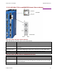
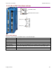
2.11.1: Safe Torque Off
All of the Xenus Plus models provide a Safe Torque Off (STO) function. Two inputs are provided
which, when de-energized, prevent the upper and lower devices in the PWM outputs from being
operated by the digital control core. This provides a positive OFF capability that cannot be
overridden by the control firmware, or associated hardware components. When the inputs are
energized (current is flowing through the input diodes), the control core will be able to control the
on/off state of the PWM outputs. Although all models have the STO feature, there are important
differences in the STO design between the single axis (XEL/XPL/XML) and the dual axis
(XE2/XP2/800-1782/800-1808) versions.
The STO circuit in the single axis models was designed using guidance from IEC 61800-5-2, an
international standard that specifies requirements for motor drive functional safety features
including STO.
The STO feature in the dual axis models was developed in accordance with several functional
safety standards and has both SIL and Category/Performance Level ratings. The design and
development of the STO feature on these models are being submitted to TÜV SÜD for approval.
Pending such approval the XE2/XP2/800-1782/800-1808 products will bear the TÜV SÜD
Functional Safety mark. For more information on STO for the Xenus Plus Dual Axis models, see
the Xenus Plus Dual-Axis STO Manual
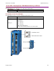
2.11.2: Faults
Overview
Xenus Plus detects and responds to a set of conditions regarded as faults, such as drive over
temperature and excessive following error. When any fault occurs, with the exception of a following
error, the drive’s PWM output stage is disabled, the fault type is recorded in the drive’s internal
error log (which can be viewed with CME 2), and the status LED changes to indicate a fault
condition exists. A digital output can also be programmed to activate on a fault condition. The
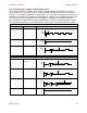
following error fault behaves with slight differences, as described in
Following Error Fault Details (p.51)
The drive’s PWM output stage can be re-enabled after the fault condition is corrected and the drive
faults are cleared. The process for clearing faults varies depending on whether the fault is
configured as non-latched or latched. The fault-clearing descriptions below apply to all faults
except for the following error fault, which is described in Following Error Fault Details (p.51)