
User guide


Xenus Plus User Guide Operational Theory
Copley Controls 34
2.8: Limit Switches
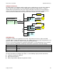
2.8.1: Use Digital Inputs to Connect Limit Switches
Limit switches help protect the motion system from unintended travel to the mechanical limits. In
the Xenus Plus Single Axis products, any of the digital inputs 1-14 (1-20 for Xenus Plus Dual Axis),
can be can be programmed as positive or negative limit switch inputs. With the drive operating as
a CAN node, an input can also be programmed as a home limit switch for CANopen homing
operations.
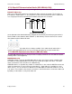
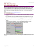
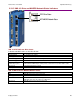
2.8.2: Diagram: Sample Placement of Limit Switches
The following diagram shows these limit switches in use on a sample motion stage.
2.8.3: How the Drive Responds to Limit Switch Activation
The drive stops any motion in the direction of an active limit switch, as described below. The
response is identical in current and velocity modes, and slightly different in position mode.
Mode
Drive Response to Active Positive (or Negative) Limit Switch
Current
Drive prohibits travel in positive (or negative) direction. Travel in the opposite direction is still allowed.
Drive status indicator flashes green at fast rate.
Warning is displayed on CME 2 Control Panel and CME 2 Control Panel limit indicator turns red.
Velocity
Position
Drive stops responding to position commands until the drive is disabled and re-enabled, or the fault is
cleared over the CANopen interface.
Drive status indicator flashes green at fast rate.
Warning is displayed on CME 2 Control Panel and CME 2 Control Panel limit indicator turns red.
Default behavior: If, after re-enabling the amp, the limit switch is still active, the drive will only allow
movement in the opposite direction.
“Hold position” behavior: If the *Hold position when limit switch is active option is set, the drive prevents any
motion while a limit switch is active.
CAUTION: If the drive is switched back to current or velocity mode with this option selected, the limit
switches will no longer function.
For more information on *Hold position when limit switch is active, see the CME 2 User Guide.
2.8.4: Using Custom Output to Signal Limit Switch Activation
In addition to the response described above, any of the drive’s digital outputs can be configured to
go active when a positive or negative limit switch is activated.
For more information, see the CME 2 User Guide.
Mechanical Limits of Motion Stage
Negative
Limit
Switch
Positive
Limit
Switch
Home
Switch