
User guide


Xenus Plus User Guide Operational Theory
Copley Controls 32
CANopen Architecture
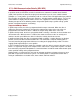
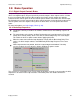
As shown below, in a CANopen motion control system, control loops are closed on the individual
drives, not across the network. A master application coordinates multiple devices, using the
network to transmit commands and receive status information. Each device can transmit to the
master or any other device on the network. CANopen provides the protocol for mapping device
and master internal commands to messages that can be shared across the network.
CAN Addressing
A CANopen network can support up to 127 nodes. Each node must have a unique and valid
seven-bit address (Node ID) in the range of 1-127. (Address 0 is reserved and should only be used
when the drive is serving as a CME 2 serial port multi-drop gateway.)
There are several basic methods for setting the CAN address, as described below. These method
can be used in any combination, producing a CAN address equal to the sum of the settings.
Addressing Method
Description
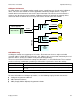
Use switch
If the address number <= 15, CAN address can be set using the CAN ADDR switch only.
Use inputs
Use the drive’s programmable digital inputs (user selects how many (1-7) and which inputs
are used).
Use programmed value
Program address into flash only.
For more information on CAN addressing, see the CME 2 User Guide.
For more information on CANopen operations, see the following Copley Controls documents:
CANopen Programmer’s Manual
CML Reference Manual
CMO (Copley Motion Objects) Programmer’s Guide
CAN port
CANopen
Software Application
Master Controller
CAN port
CANopen
Xenus
Amplifier
I/O
CAN port
CANopen
Other
CANopen
Device
Status
Local Control
Motor
Sensor
Feedback
Local Control
Motor
Sensor
Feedback
CAN port
CANopen
Xenus
Amplifier
I/O
Control
CAN Network