
User guide

Xenus Plus User Guide Operational Theory
Copley Controls 27
2.6.2: PWM Input
Two Formats
The drive can accept a pulse width modulated signal (PWM) signal to provide a current command
in current mode and a velocity command in velocity mode. The PWM input can be programmed for
two formats: 50% duty cycle (one-wire) and 100% duty cycle (two-wire).
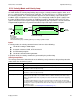
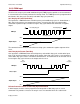
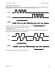
50% Duty Cycle Format (One-Wire)
The input takes a PWM waveform of fixed frequency and variable duty cycle. As shown below, a
50% duty cycle produces zero output from the drive. Increasing the duty cycle toward 100%
commands a positive output, and decreasing the duty cycle toward zero commands a negative
output.
The command can be inverted so that increased duty cycle commands negative output and vice
versa.
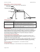
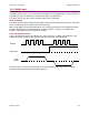
100% Duty Cycle Format (Two-Wire)
One input takes a PWM waveform of fixed frequency and variable duty cycle, and the other input
takes a DC level that controls the polarity of the output. A 0% duty cycle creates a zero command,
and a 100% duty cycle creates a maximum command level. The command can be inverted so that
increasing the duty cycle decreases the output and vice versa.
Failsafe Protection from 0 or 100% Duty Cycle Commands
In both formats, the drive can be programmed to interpret 0 or 100% duty cycle as a zero
command. This provides a measure of safety in case of a controller failure or a cable break.
Decreasing Duty Cycle Increasing Duty Cycle
Max -
Max +
0
PWM Input
Amplifier Output
50 % Duty Cycle
Max +
0
PWM Input
Amplifier Output
Direction Input
100%
Duty Cycle
100%
Duty Cycle
Min -