
User guide

Xenus Plus User Guide Operational Theory
Copley Controls 18
2.5: Operating Modes
2.5.1: Modes and Control Loops
Nesting of Control Loops and Modes
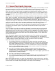
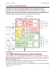
Copley Controls drives use up to three nested control loops - current, velocity, and position - to
control a motor in three associated operating modes.
Control Loops Illustration
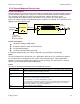
In position mode, the drive uses all three loops. As shown below, the position loop drives the
nested velocity loop, which drives the nested current loop.
In velocity mode, the velocity loop drives the current loop. In current mode, the current loop is
driven directly by external or internal current commands.
Basic Attributes of All Control Loops
These loops (and servo control loops in general) share several common attributes:
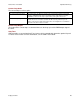
Loop Attribute
Description
Command input
Every loop is given a value to which it will attempt to control. For example, the velocity loop
receives a velocity command that is the desired motor speed.
Limits
Limits are set on each loop to protect the motor and/or mechanical system.
Feedback
The nature of servo control loops is that they receive feedback from the device they are
controlling. For example, the position loop uses the actual motor position as feedback.
Gains
These are constant values that are used in the mathematical equation of the servo loop. The
values of these gains can be adjusted during drive setup to improve the loop
performance. Adjusting these values is often referred to as tuning the loop.
Output
The loop generates a control signal. This signal can be used as the command signal to another
control loop or the input to a power drive.
Target
Position
Position
Command
Actual CurrentDerived VelocityActual Position
Velocity
Command
Current
Command
Limited
Velocity
Limited
Current
PWM
Command
Trajectory
Generator
Position
Loop
Velocity
Limiter
Current
Limiter
Current
Loop
Motor/
Sensors
Limits
Velocity
Loop
FILTER
FILTER