
User guide

Xenus Plus User Guide Operational Theory
Copley Controls 16
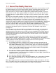
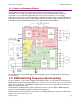
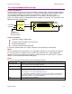
2.1.3: Power and Grounding Diagram
The graphic below shows the different power sections within the Xenus Plus drives and the
isolation barriers between them. Note that the diagram shows the power and feedback
connections to one motor and applies directly to the single axis model. Although not shown,
connections to a second motor (applicable for the dual axis drive models) are essentially
duplicates of the first. The second motor power connections originate from a second PWM inverter
in the Mains circuit block and the second motor feedback connections originate from a second set
of Feedback Power and Decoding circuitry in the Signal GND referenced block.
The isolation barriers associated with the general purpose inputs and outputs or the STO inputs
are not shown.
2.2: PWM Switching Frequency Synchronizing
In some situations, such as when sampling small analog signals, it is desirable to synchronize the
PWM switching frequency among multiple drives. In these cases, one drive serves as a master for
one or more slave drives. The PWM sync output of the master sends a signal that is received as a
PWM sync input by each slave.
Alternatively the distributed clock feature of EtherCAT can be used to establish PWM switching
frequency synchronization among the network connected drives.
Note that when the STO function is active, there is no PWM switching or current at the drive motor
outputs. See Safe Torque Off (p. 47).