
User guide

Xenus Plus User Guide Operational Theory
Copley Controls 15
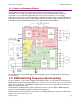
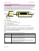
2.1: Drive Internal Power
Power distribution within Xenus Plus is divided into three sections: +24 Vdc, logic/signal, and high
voltage. Each is isolated from the other.
2.1.1: Logic/Signal Power
An internal DC/DC converter operates from the +24 Vdc Logic Supply input and creates the
required logic/signal operating voltages, the isolated voltages required for the high-voltage control
circuits, and a +5 Vdc supply for powering the motor encoder and Hall circuits.
With the Xenus Plus Single Axis drives, digital inputs IN1~6 and IN15, analog inputs AIN1~3,
digital outputs OUT1~3, Hall inputs and encoder inputs are all referenced to signal ground. Inputs
IN7~10 and IN11~14 are groups of four opto-isolated inputs with a common terminal for each
group. Outputs OUT4~5 are two-terminal Darlington opto-isolators. The brake output OUT6 is
opto-isolated and referenced to the +24Vdc return. The CAN interface is optically isolated.
With the Xenus Plus Dual Axis drives, digital inputs IN1~5, IN10~11, and IN16~22, analog inputs
AIN1~2, Hall inputs, and encoder inputs are referenced to signal ground. Inputs IN6~9 and
IN16~19 are two groups of four opto-isolated inputs with a common terminal for each group. Brake
outputs OUT6~7 are opto-isolated and referenced to the 24V return. Outputs OUT1~5 are two-
terminal MOSFET SSRs. The CAN interface is optically isolated.
Deriving internal operating voltages from a separate source enables the drive to stay on-line when
the mains have been disconnected for emergency-stop or operator-intervention conditions. This
allows CAN bus and serial communications to remain active so that the drive can be monitored by
the control system while the mains power is removed.
2.1.2: High Voltage
Mains power drives the high-voltage section. It is rectified and capacitor-filtered to produce the DC
bus: the DC “link” power that drives the PWM inverter, where it is converted into the voltages that
drive a three-phase brushless or DC brush motor. An internal solid-state switch, together with an
external power resistor, provides dissipation during regeneration when the mechanical energy of
the motor is converted back into electrical energy. This prevents charging the internal capacitors to
an overvoltage condition.