
User guide


Xenus Plus User Guide Wiring
Copley Controls 107
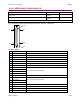
…Pin Description, continued:
20
A-MultiEnc /B
Programmable differential input/output port.
21
A-MultiEnc /A
Programmable differential input/output port.
22
Signal ground
Signal ground reference for inputs and outputs.
23
B +5Vdc Out4
24
B-MultiEnc /S
Programmable differential input/output port.
25
B-MultiEnc /X
26
B-MultiEnc /B
27
B-MultiEnc /A
28
N/C
29
N/C
30
IN15 Diff4(-)
Mode dependent dedicated input.
31
Signal ground
Signal ground reference for inputs and outputs.
32
A +5Vdc Out3
33
A-MultiEnc S
Programmable differential input/output port.
34
A-MultiEnc X
35
A-MultiEnc B
36
A-MultiEnc A
37
Signal ground
Signal ground reference for inputs and outputs.
38
B +5Vdc Out4
39
B-MultiEnc S
Programmable differential input/output port.
40
B-MultiEnc X
41
B-MultiEnc B
42
B-MultiEnc A
43
N/C
44
Signal ground
Signal ground reference for inputs and outputs.
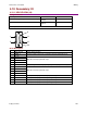
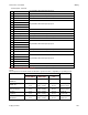
Mode Dependent Dedicated Inputs
Axis A
These inputs are for Axis A and are dedicated to specific functions, depending on operating mode.
Mode
Selected Command Source
Function
Digital Input
Single Ended
Digital Input
Differential
Multi-Mode
Port
Current & Velocity
PWM 50%
IN 4
IN2(+) & IN3(-)
A & /A
PWM Input
Current & Velocity
PWM 100%
IN 4
IN2(+) & IN3(-)
A & /A
PWM Input
IN 5
IN4(+) & IN5(-)
B & /B
Direction Input
Position
Pulse & Direction
IN 4
IN2(+) & IN3(-)
A & /A
Pulse Input
IN 5
IN4(+) & IN5(-)
B & /B
Direction Input
Position
Up/Down
IN 4
IN2(+) & IN3(-)
A & /A
Count Up
IN 5
IN4(+) & IN5(-)
B & /B
Count Down
Position
Quadrature
IN 4
IN2(+) & IN3(-)
A & /A
Channel A
IN 5
IN4(+) & IN5(-)
B & /B
Channel B