
User guide


Xenus XTL User Guide Quick Setup with CME 2
Copley Controls Corp. 87
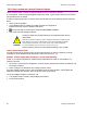
5.6.4: Standard Digital Outputs
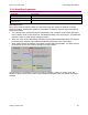
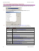
5.6.4.1 Click the Digital Outputs tab of the Input/Output screen. A typical Digital Outputs screen is
shown below. (Features may vary with amplifier model and configuration.)
Grey light:
Output is not active
Hi/Lo state of output
Red light:
Output is active
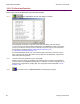
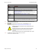
5.6.4.2 Choose any of the following functions for any output. OUT4 is recommended for brake
function.
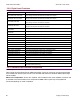
Output Function Description For More Information
Not Configured No function assigned. Output remains high.
Fault Active High Output goes high when at least one fault is
detected.
Fault-Active Low Output goes low when at least one fault is
detected.
Faults (p. 26).
Brake-Active High Output goes high to activate the brake.
Brake-Active Low Output goes low to activate the brake.
Brake Operation (p. 23).
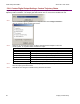
PWM Sync Output
(OUT1 only)
The PWM synchronization output. Synchronizing PWM Switching
Frequency (p. 8) and Digital
Input Functions (p. 86).
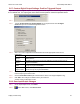
Custom Event See Custom Digital Output Settings: Custom Event (p. 88).
Custom Trajectory
Status
See Custom Digital Output Settings: Custom Trajectory Status (p. 90).
Custom Position
Triggered Output
See Custom Digital Output Settings: Position Triggered Output (p. 91).
Program Control
Active High
Output state controlled by CVM or external program.
Program Control
Active Low
Output state controlled by CVM or external program