
User guide


Xenus XTL User Guide Wiring
Copley Controls Corp. 49
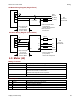
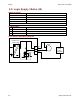
AC Mains Wiring Diagram (Single-Phase)
Amplifier
L1
L2
Fus es**
L1 (Line)
L2 (Neut)
Earth
Ground
Keep wire length
as short as
possible. Not to
exceed 1 Meter.
1
Ø
47-63 Hz
100-240 VAC
** Not required on
a neutral line.
J1-4
J1-1
J1-2
J1
* Filter Concepts SF20L
(or equivalent)
used for CE compliance
L
O
A
D
L
I
N
E
Line Filter*
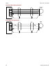
AC Mains Wiring Diagram (Three-Phase)
A
C
B
Line Filter*
Fus es
L3
L2
Earth
Ground
3
Ø
47-63 Hz
100-240 VAC
Gnd
A
C
B
L1
L3
Keep wire length
as short as
possible. Not to
exceed 1 Meter.
Amplifier J1
L1
L2
J1-4
J1-1
J1-2
* Filter Concepts 3F15
(or equivalent)
used for CE compliance
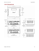
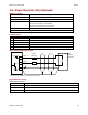
4.3: Motor (J2)
Mating Connector
Description Euro-style, 4 position, 5.0 mm pluggable female terminal block
Manufacturer PN
Wago: 51118008 or 721-104/026-047/RN01-0000
Wire Size 22 - 12 AWG
Recommended Wire 18 A models: 14 AWG, 600 V
36 A and 40 A models: 12 AWG, 600 V
Shielded cable required for CE compliance
Wire Insertion/Extraction Tool Wago: 231-131
Standard connector and tool are included in connector kit XTL-CK or XTL-CA
Pin Description
Pin Signal Function
1 Ground Motor frame ground and cable shield
2 W Phase W output of amplifier
3 V Phase V output of amplifier (use for DC motor connection)
4 U Phase U output of amplifier (use for DC motor connection)