
User guide

Xenus XTL User Guide Specifications
Copley Controls Corp. 39
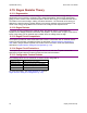
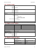
3.10: Brake Output
Channels 1
Type Current-sinking MOSFET, optically isolated from control/logic ground.
Referenced to +24 Vdc logic supply.
Internal fly back diode to +24 Vdc.
Maximum Sink Current 1 A
Low Level Output Resistance
<0.2
Function Primary function is brake control.
May be programmed to other functions.
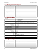
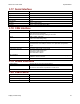
3.11: Encoder Power Supply Output
Voltage Output +5 Vdc ±2%
Maximum Current Output 400 mA
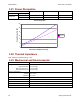
Short Circuit Protection Fold-back current limiting
Function Provides power for motor encoder and/or Hall switches.
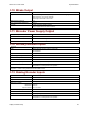
3.12: Primary Encoder Inputs
Channels 3
Type Differential RS-422 line receiver w/ RC filter
Non-isolated
Signals A, /A, B, /B, X*, /X*
Input Voltage Range ±7 Vdc
Differential Input Threshold ±0.2 Vdc
Termination Resistance
121
Maximum Frequency 5 MHz Line (20 Mcount/sec)
Function Incremental or analog encoder or resolver required for sinusoidal commutation
and position or velocity modes of operation.
* X is equivalent to Marker, Index, or Z channels, depending on the encoder manufacturer. This channel is only
required in certain homing modes while under CAN control.
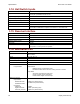
3.13: Analog Encoder Inputs
Channels 2
Type Differential, non-isolated
Signals Sin, cosine
Nominal Voltage 1 Vdc-pk
Maximum Voltage
Differential
Input to Ground
±0.6 Vdc
0 to +3.5 Vdc
Differential Input Impedance
121
Bandwidth 230 kHz
Interpolation 1 to 256, programmable
Function Incremental or analog encoder or resolver required for sinusoidal commutation
and position or velocity modes of operation.