
User guide

Xenus XTL User Guide Operational Theory
Copley Controls Corp. 33
2.14: Outputs
2.14.1: Digital Outputs
The amplifier has four programmable digital outputs. Three of the outputs (OUT1 - 3) are general-
purpose outputs. The fourth (OUT4) is specifically designed as a brake output but can be
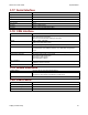
programmed to perform any of the functions. For a list of digital output functions, see Standard
Digital Outputs (p. 87).
The general-purpose outputs are open-drain MOSFETs, each with a pull-up resistor, in series with
a diode, connected to the amplifier’s internal +5 Vdc supply. This design allows the outputs to be
directly connected to optically isolated PLC inputs that reference a voltage higher than
+5 Vdc, typically +24 Vdc. The diode prevents current flow between the +24 Vdc supply and the
internal +5 Vdc supply though the pull-up resistor. This current, if allowed to flow, could turn on the
PLC input, giving a false indication of the amplifier’s true output state.
The general-purpose outputs require an external fly-back diode to be installed across any
inductive loads, such as relays, that are connected to them.
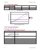
The brake output (OUT4) is described in Brake Operation (p. 23).