
User guide

Xenus XTL User Guide Operational Theory
Copley Controls Corp. 15
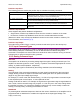
Position Loop Gains
The following gains are used by the position loop to calculate the velocity command:
Gain Description
Pp - Position loop proportional The loop calculates the position error as the difference between the actual and
limited position values. This error in turn is multiplied by the proportional gain value.
The primary effect of this gain is to reduce the following error.
Vff - Velocity feed forward The value of the profile velocity is multiplied by this value. The primary effect of this
gain is to decrease following error during constant velocity.
Aff - Acceleration feed forward The value of the profile acceleration is multiplied by this value. The primary effect of
this gain is to decrease following error during acceleration and deceleration.
Gain Multiplier The output of the position loop is multiplied by this value before being passed to the
velocity loop.
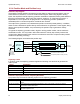
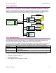
Position Loop Feedback
Xenus supports two position feedback configurations
• Single sensor. Position loop feedback comes from the encoder or resolver on the motor.
• Dual sensor. Position loop feedback comes from the encoder attached to the load.
(Note that in either case, velocity loop feedback comes from the motor encoder or resolver.) For
more information, see Feedback (p. 8).
Position Loop Output
The output of the position loop is a velocity command used as the input to the velocity loop.
2.5.5: Input Command Types
The amplifier can be controlled by a variety of external sources: analog voltage or digital inputs,
CAN network (CANopen or DeviceNet), or over an RS-232 serial connection using ASCII
commands. The amplifier can also function as a stand-alone motion controller running an internal
CVM program or using its internal function generator.
2.5.6: Analog Command Input
Overview
The amplifier can be driven by an analog voltage signal through the analog command input. The
amplifier converts the signal to a current, velocity, or position command as appropriate for current,
velocity, or position mode operation, respectively.
The analog input signal is conditioned by the scaling, dead band, and offset settings.
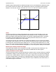
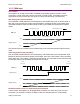
Scaling
The magnitude of the command generated by an input signal is proportional to the input signal
voltage. Scaling controls the input-to-command ratio, allowing the use of an optimal command
range for any given input voltage signal range.
For example, in current mode, with default scaling, +10 Vdc of input generates a command equal
to the amplifier’s peak current output; +5 Vdc equals half of that.
Scaling could also be useful if, for example, the signal source generates a signal range between 0
and +10 Vdc, but the command range only requires +7.5 Vdc of input. In this case, scaling allows
the amplifier to equate +7.5 Vdc with the amplifier’s peak current (in current mode) or maximum
velocity (in velocity mode), increasing the resolution of control.
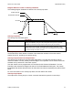
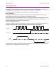
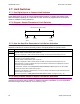
Dead Band
To protect against unintended response to low-level line noise or interference, the amplifier can be
programmed with a “dead band” to condition the response to the input signal voltage. The