
User guide

Xenus XTL User Guide Operational Theory
Copley Controls Corp. 13
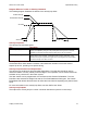
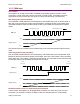
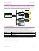
Diagram: Effects of Limits on Velocity Command
The following diagram illustrates the effects of the velocity loop limits.
Commanded Velocity
Limited Velocity
Vel Limit
Accel Limit Decel Limit
Velocity Loop Gains
The velocity loop uses these gains:
Gain Description
Vp - Velocity loop proportional The velocity error (the difference between the actual and the limited commanded
velocity) is multiplied by this gain. The primary effect of this gain is to increase
bandwidth (or decrease the step-response time) as the gain is increased.
Vi - Velocity loop integral The integral of the velocity error is multiplied by this value. Integral gain reduces the
velocity error to zero over time. It controls the DC accuracy of the loop, or the
flatness of the top of a square wave signal. The error integral is the accumulated
sum of the velocity error value over time.
Velocity Loop Gains Scalar
The Enable Gains Scalar feature increases or decreases the resolution of the units used to
express Vp and Vi, providing more precise tuning.
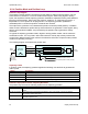
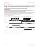
Velocity Loop Command and Output Filters
The velocity loop contains two programmable digital filters. The input filter should be used to
reduce the effects of a noisy velocity command signal. The output filter can be used to reduce the
excitation of any resonance in the motion system.
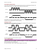
Two filter classes can be programmed: the Low-Pass and the Custom Bi-Quadratic. The Low-
Pass filter class includes the Single-Pole and the Two-Pole Butterworth filter types. The Custom
Bi-Quadratic filter allows advanced users to define their own filters incorporating two poles and two
zeros.
For more information on the velocity loop filters, see the CME 2 User Guide.
Velocity Loop Outputs
The output of the velocity loop is a current command used as the input to the current loop.