
User guide

Xenus XTL User Guide Xenus Filter
Copley Controls Corp. 161
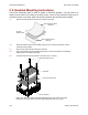
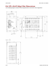
D.5.3: Cable Notes
1 Keep the Edge Filter J1 to Xenus J2 cable as short as possible. A typical length is 7 inches.
2 To reduce noise, twisted shielded cable must be used and the signal cables should not be
bundled in the same conduit.
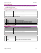
D.5.4: Input (J1) From Amplifier
Mating Connector
Description Euro-style, 5 position, 5.0 mm pluggable female terminal block
Manufacturer PN Wago 51118042 or 721-105/026-047/RN01-0000
Wire Size 22 - 12 AWG
Recommended Wire 12 AWG, 600 V
(Shielded cable used for CE compliance)
Wire Insertion/Extraction Tool Wago 231-131
Connector and tool are included in connector kit XTL-FK.
Pin Description
Pin Signal Function
1 Ground Chassis ground and cable shield
2 Phase W Phase W input from amplifier
3 Phase V Phase V input from amplifier (use for DC motor connection)
4 Phase U Phase U input from amplifier (use for DC motor connection)
5 --- No connection
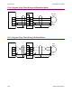
D.5.5: Output (J2) To Motor
Mating Connector
Description Euro-style, 4 position, 5.0 mm pluggable female terminal block.
Manufacturer PN Wago 51118008 or 721-104/026-047/RN01-0000
Wire Size 22 - 12 AWG
Recommended Wire 12 AWG, 600 V
(Shielded cable used for CE compliance)
Wire Insertion/Extraction Tool Wago 231-131
Connector and tool are included in connector kit XTL-FK.
Pin Description
Pin Signal Function
1 Ground Chassis ground and cable shield
2 Phase W Phase W output to motor
3 Phase V Phase V output to motor (use for DC motor connection)
4 Phase U Phase U output to motor (use for DC motor connection)