
User guide

Using CME 2 Xenus XTL User Guide
130 Copley Controls Corp.
6.4: Control Panel
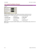
6.4.1: Control Panel Overview
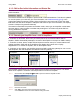
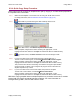
To access the control panel, click the Control Panel icon ( ) on the Main screen.
Each of the features labeled below is described in the following sections.
Status indicators
Message box
Display error log
Monitor real-time amplifier values
and operational mode
Control functions
Jog mode controls
Red if fault
is active
Yellow if warning
is active
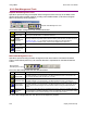
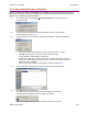
6.4.2: Status Indicators and Messages
The Status area includes status indicator lights (described below) and a message box. All green
lights indicate the amplifier is enabled and ready to accept motion commands.
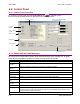
Indicator States/Description
Motor Output State of the PWM output stage. Red if the output stage is inactive (disabled)
Hardware
Enabled
State of the hardware enable input(s). Red if one or more enable inputs are inactive.
Software
Enabled
State of the software enable. Red if the amplifier is disabled by software.
Positive Limit State of the positive limit switch input. Red indicates an activated positive limit switch.
Negative Limit State of the negative limit switch input. Red indicates an activated negative limit switch.
Software Limits State of the software limits. Red indicates an activated software limit.
Motor Phase Indicates a motor phasing error. Red indicates a motor phasing error exists.
Motion Abort
Input
State of the programmed Motion Abort Input. Red indicates the input is active.
CVM Control
Program
Status of the CVM Control Program.
Home Indicates whether the axis has successfully been referenced (homed).
CAN Status The status of the CAN Bus. Yellow indicates a CAN warning limit reached. Red indicates a bus
error detected. (If the CAN Status indicator is replaced by the DeviceNet Status indicator, see the
Copley DeviceNet Programmer’s Guide.)
Continued…