
User guide

Xenus XTL User Guide Using CME 2
Copley Controls Corp. 123
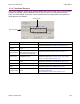
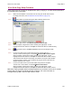
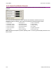
6.1.4: Functional Diagram
The functional diagram, shown below, provides button-click access to most of the screens used to
configure an amplifier. It also indicates the flow of control from input, across all active control
loops, to motor/feedback. Only those control loop buttons that are appropriate to the operational
mode appear on the diagram.
Input Command
Control Loops
Name Description For More Information
Input/Output
Opens Input/Output screen. Theory: Inputs (p. 32) and Outputs (p. 33).
Programming instructions: Amplifier Configuration (p. 85).
CVM Control
Program
Opens Copley Virtual Machine
screen.
Copley Indexer Program User Guide.
Input Command
Configure the input command.
Button label varies depending on
the selected control loop input.
Theory: Input Command Types (p. 15.
Programming instructions: Basic Setup Screen (p. 73.
Control Loops
Each opens a control loop
configuration screen.
Theory: Operating Modes (p. 9).
Programming instructions: Current Loop (p. 108), Velocity
Loop (p. 112), and Position Loop (p. 114).
Motor/Feedback
Opens the Motor/Feedback
screen.
Theory: Feedback (p. 8).
Programming instructions: Motor/Feedback Setup (p. 76).
Home Configure and test homing. Home Function (p. 136).
Configure
Regen
Opens Regen Resistor screen. Theory: Regen Resistor Theory (p. 34).
Programming instructions: Regen Resistor (p. 94).
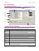
Configure Faults
Opens Fault Configuration
screen.
Theory: Faults (p. 26).
Programming instructions:
Non-Latched and Latched Custom Outputs (p. 92).