
User guide

Xenus XTL User Guide Quick Setup with CME 2
Copley Controls Corp. 101
5.7.4: CAN Interface
For more information on CAN see CANopen Operation (p. 20).
For information on DeviceNet, see the Copley DeviceNet Programmer’s Guide.
5.7.4.1 V
erify that the following connections are wired according to the instructions in
CAN Bus (J6) (p. 54):
1. J6 "CAN" CANopen cable
2. J6 "CAN" Termination plug
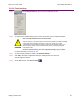
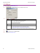
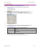
5.7.4.2 Click CAN Configuration to open the CAN Configuration screen. (If CAN
is not the Position Loop Input, choose AmplifierCAN Configuration instead.)
Here is a typical CAN Configuration screen. (Features may vary based on amplifier model
and configuration.)
5.7.4.3 Set Network Type to CAN.
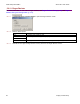
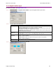
5.7.4.4 Choose a Bit Rate and choose any combination of address sources (Switch, Inputs, and
Programmed Value). The address is the sum of the values from these sources.
See CAN Addressing (p. 21).
5.7.4.5 For each source selected, perform the additional steps described below.
Source Additional Steps
Use Switch Verify the S1 switch setting. (Assigns values for Bit 0 – Bit 3 of CAN
address.)
Use Inputs
Enter the Number of inputs. Choose the input that will represent each
CAN address bit.
Use Programmed
Value
Enter the Programmed value.
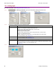
5.7.4.6 Click OK to close the screen and save the changes to flash.
NOTE: CAN address and bit rate are changed only after power-up or reset.