Xenus XTL™ User Guide P/N 95-00875-000 Revision 1 December 2007
Xenus XTL User Guide This page for notes.
TABLE OF CONTENTS About This Manual ............................................................................................................................................................................... iii 1: Introduction ................................................................................................................................................................................. 1 1.1: Amplifier .....................................................................................
Table of Contents A: B: C: D: E: F: ii Xenus XTL User Guide 6.1: CME 2 Overview................................................................................................................................................................. 120 6.2: Manage Amplifier and Motor Data ...................................................................................................................................... 125 6.3: Downloading Firmware ............................................................
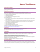
ABOUT THIS MANUAL Overview and Scope This manual describes the operation and installation of the Xenus XTL amplifier manufactured by Copley Controls Corporation. Related Documentation For important setup and operation information, see the CME 2 User Guide.
About this Manual Xenus XTL User Guide Product Warnings Observe all relevant state, regional, and local safety regulations when installing and using this product. For safety and to assure compliance with documented system data, only Copley Controls Corporation should perform repairs to amplifiers. ! DANGER: Hazardous voltages. Exercise caution when installing and adjusting. Failure to heed this warning can cause equipment damage, injury, or death. DANGER ! Risk of electric shock.
Xenus XTL User Guide About this Manual Revision History Revision Date DECO# Comments 1 November 2007 16236 Initial release. Copley Controls Corp.
About this Manual Xenus XTL User Guide This page for notes. vi Copley Controls Corp.
CHAPTER 1: INTRODUCTION This chapter provides an overview of the Copley Controls Xenus XTL amplifier. Contents include: Title Page 1.1: Amplifier ................................................................................................................................................................................. 2 1.2: CME 2 ...............................................................................................................................................................................
Introduction Xenus XTL User Guide 1.1: Amplifier Xenus provides 100% digital control of brushless or brush motors in an off-line powered package. It can also control a Copley Controls ServoTube motor. Xenus can operate from single or threephase mains with a continuous power output of up to 4 kW. Xenus is offered in three versions to support three types of feedback devices. The standard version supports digital quadrature encoders. The –S version supports analog sin/cos encoders.
Xenus XTL User Guide Introduction 1.2: CME 2 Amplifier commissioning is fast and simple using Copley Controls CME 2 software. CME 2 communicates with Xenus via an RS-232 link, and all of the operations needed to configure the amplifier are accessible through CME 2. The multi-drop feature allows CME 2 to use a single RS-232 serial connection to one amplifier as a gateway to other amplifiers linked together by CAN bus connections.
Introduction 4 Xenus XTL User Guide Copley Controls Corp.
CHAPTER 2: OPERATIONAL THEORY This chapter describes the basics of Xenus operation. Contents include: Title Page 2.1: Amplifier Internal Power.......................................................................................................................................................... 6 2.2: Synchronizing PWM Switching Frequency.............................................................................................................................. 8 2.3: Commutation Modes ...................
Operational Theory Xenus XTL User Guide 2.1: Amplifier Internal Power Power distribution within Xenus is divided into three sections: +24 Vdc, logic/signal, and high voltage. Each is isolated from the other. 2.1.1: Logic/Signal Power An internal DC/DC converter operates from the +24 Vdc Logic Supply input and creates the required logic/signal operating voltages, the isolated voltages required for the high-voltage control circuits, and a +5 Vdc supply for powering the motor encoder and Hall circuits.
Xenus XTL User Guide Operational Theory 2.1.
Operational Theory Xenus XTL User Guide 2.2: Synchronizing PWM Switching Frequency In some situations, such as when sampling small analog signals, it is desirable to synchronize the PWM switching frequency among multiple amplifiers. In these cases, one amplifier serves as a master for one or more slave amplifiers. The PWM sync output of the master sends a signal that is received as a PWM sync input by each slave. 2.
Xenus XTL User Guide Operational Theory 2.5: Operating Modes 2.5.1: Modes and Control Loops Nesting of Control Loops and Modes Copley Controls amplifiers use up to three nested control loops - current, velocity, and position - to control a motor in three associated operating modes. Control Loops Illustration In position mode, the amplifier uses all three loops. As shown below, the position loop drives the nested velocity loop, which drives the nested current loop.
Operational Theory Xenus XTL User Guide 2.5.2: Current Mode and Current Loop Current Loop Diagram As shown below, the “front end” of the current loop is a limiting stage. The limiting stage accepts a current command, applies limits, and passes a limited current command to the summing junction. The summing junction takes the limited current command, subtracts the actual current (represented by the feedback signal), and produces an error signal.
Xenus XTL User Guide Operational Theory Current Loop Gains The current loop uses these gains: Gain Description Cp - Current loop proportional The current error (the difference between the actual and the limited commanded current) is multiplied by this value. The primary effect of this gain is to increase bandwidth (or decrease the step-response time) as the gain is increased. Ci - Current loop integral The integral of the current error is multiplied by this value.
Operational Theory Xenus XTL User Guide 2.5.3: Velocity Mode and Velocity Loop Velocity Loop Diagram As shown below, the velocity loop limiting stage accepts a velocity command, applies limits, and passes a limited velocity command to the input filter. The filter then passes a velocity command to the summing junction. The summing junction subtracts the actual velocity, represented by the feedback signal, and produces an error signal.
Xenus XTL User Guide Operational Theory Diagram: Effects of Limits on Velocity Command The following diagram illustrates the effects of the velocity loop limits. Limited Velocity Commanded Velocity Vel Limit Accel Limit Decel Limit Velocity Loop Gains The velocity loop uses these gains: Gain Description Vp - Velocity loop proportional The velocity error (the difference between the actual and the limited commanded velocity) is multiplied by this gain.
Operational Theory Xenus XTL User Guide 2.5.4: Position Mode and Position Loop Position Loop Diagram The amplifier receives position commands from the digital or analog command inputs, over the CAN interface or serial bus, or from the CVM Control Program. When using digital or analog inputs, the amplifier's internal trajectory generator calculates a trapezoidal motion profile based on trajectory limit parameters.
Xenus XTL User Guide Operational Theory Position Loop Gains The following gains are used by the position loop to calculate the velocity command: Gain Description Pp - Position loop proportional The loop calculates the position error as the difference between the actual and limited position values. This error in turn is multiplied by the proportional gain value. The primary effect of this gain is to reduce the following error.
Operational Theory Xenus XTL User Guide amplifier treats anything within the dead band ranges as zero, and subtracts the dead band value from all other values. For instance, with a dead band of 100 mV, the amplifier ignores signals between –100 mV and +100 mV, and treats 101 mV as 1 mV, 200 mV as 100 mV, and so on.
Xenus XTL User Guide Operational Theory 2.5.7: PWM Input Two Formats The amplifier can accept a pulse width modulated signal (PWM) signal to provide a current command in current mode and a velocity command in velocity mode. The PWM input can be programmed for two formats: 50% duty cycle (one-wire) and 100% duty cycle (two-wire). 50% Duty Cycle Format (One-Wire) The input takes a PWM waveform of fixed frequency and variable duty cycle.
Operational Theory Xenus XTL User Guide 2.5.8: Digital Input Three Formats In position mode, the amplifier can accept position commands via two digital inputs, using one of these signal formats: pulse and direction, count up/count down, and quadrature. In all three formats, the amplifier can be configured to invert the command. Pulse Smoothing In position mode, the amplifier’s trajectory generator ensures smooth motion even when the command source cannot control acceleration and deceleration rates.
Xenus XTL User Guide Operational Theory Count Up/Count Down Format In the count up/count down format, one input takes each pulse as a positive step command, and another takes each pulse as a negative step command, as shown below. Up Input Down Input Velocity Command The amplifier can be set to increment position on the rising or falling edge of the signal. Stepping resolution can be programmed for electronic gearing.
Operational Theory Xenus XTL User Guide 2.6: CANopen Operation 2.6.1: CAN Network and CANopen Profiles for Motion In position mode, the amplifier can take instruction over a two-wire Controller Area Network (CAN). CAN specifies the data link and physical connection layers of a fast, reliable network. CANopen is a set of profiles (specifications) built on a subset of the CAN application layer protocol.
Xenus XTL User Guide Operational Theory 2.6.3: Architecture As shown below, in a CANopen motion control system, control loops are closed on the individual amplifiers, not across the network. A master application coordinates multiple devices, using the network to transmit commands and receive status information. Each device can transmit to the master or any other device on the network.
Operational Theory Xenus XTL User Guide 2.7: Limit Switches 2.7.1: Use Digital Inputs to Connect Limit Switches Limit switches help protect the motion system from unintended travel to the mechanical limits. Any of the digital inputs 2-12 can be can be programmed as positive or negative limit switch inputs. With the amplifier operating as a CAN node, an input can also be programmed as a home limit switch for CANopen homing operations. 2.7.
Xenus XTL User Guide Operational Theory 2.8: Brake Operation 2.8.1: Digital Output Controls Brake Many control systems employ a brake to hold the axis when the amplifier is disabled. Digital output 4 (OUT4) is designed specifically for a brake output. (Other outputs can be used for brake control, but OUT4 is recommended.) Unlike the other outputs, OUT4 is optically isolated from the control signals and has an internal fly back diode connected to the +24 Vdc input.
Operational Theory Xenus XTL User Guide 2.9: Status Indicators 2.9.1: Amplifier and CAN Interface Status Indicators The amplifier’s status indicator is a bicolor LED labeled STATUS on the amplifier front panel. The CAN interface status indicator is a bicolor LED labeled CAN. Locations are shown below. Xenus Status Indicator CAN Status Indicator 2.9.2: Amplifier Status Indicator Operation Amplifier status indicator color/blink codes are described below.
Xenus XTL User Guide Operational Theory 2.9.3: CAN Interface Status Indicator Operation The amplifier status indicator color/blink codes comply with CAN Indicator Specification 303-3 as described below. Note that green and red codes are often interlaced, each indicating a different set of conditions. The green codes indicate the CANopen state machine mode of operation (preoperational, operational, or stopped). The red codes indicate the status of the physical bus (warning or error conditions).
Operational Theory Xenus XTL User Guide 2.10: Protection 2.10.1: Faults Overview Xenus detects and responds to a set of conditions regarded as faults, such as amplifier over temperature and excessive following error. When any fault occurs, with the exception of a following error, the amplifier’s PWM output stage is disabled, the fault type is recorded in the amplifier’s internal error log (which can be viewed with CME 2), and the status LED changes to indicate a fault condition exists.
Xenus XTL User Guide Operational Theory Fault Descriptions The set of possible faults is described below. For details on limits and ranges, see Fault Levels (p. 41). Fault Description Fault Occurs When… Fault is Corrected When… *Amplifier Over Temperature Amplifier's internal temperature exceeds specified temperature. Power module temperature falls below specified temperature. Motor Phasing Error Encoder-based phase angle does not agree with Hall switch states.
Operational Theory Xenus XTL User Guide 2.11: Position and Velocity Errors 2.11.1: Error-Handling Methods In position mode, any difference between the limited position output of the trajectory generator and the actual motor position is a position error. The amplifier’s position loop uses complementary methods for handling position errors: following error fault, following error warning, and a positiontracking window.
Xenus XTL User Guide Operational Theory 2.11.5: Following Error Fault Details Position Error Reaches Fault Level As described earlier, position error is the difference between the limited position output of the trajectory generator and the actual position. When position error reaches the programmed Following Error Fault level, the amplifier faults (unless the following error fault is disabled.) As with a warning, a status bit is set. In addition, the fault is recorded in the error log.
Operational Theory Xenus XTL User Guide 2.11.6: Tracking Window Details Proper Tracking Over Time As described earlier, position error is the difference between the limited position output of the trajectory generator and the actual position. Velocity error is the difference between commanded and actual velocity. When the position or velocity error exceeds the programmed tracking window value, a status word bit is set.
Xenus XTL User Guide Operational Theory 2.12: Communication 2.12.1: Communication Interfaces As described below, the amplifier features two communication interfaces, each used for different purposes. Interface Description RS-232 port The amplifier features a three-wire RS-232 port. CME 2 software communicates with the amplifier using a binary protocol over this link for commissioning, adjustments, and diagnostics. In addition, ASCII commands can be issued over the serial port.
Operational Theory Xenus XTL User Guide 2.13: Inputs 2.13.1: Digital Inputs The amplifier has twelve digital inputs (IN1-IN12). Eleven of them appear on the control connector. IN5 appears on the feedback connector, and is intended for the motor over temperature switch (although it can be programmed for any function). For a list of input functions, see Digital Input Functions (p. 86 ). 2.13.2: Input Filters Two types of input RC filters are used: GP (general-purpose) and HS (high-speed).
Xenus XTL User Guide Operational Theory 2.14: Outputs 2.14.1: Digital Outputs The amplifier has four programmable digital outputs. Three of the outputs (OUT1 - 3) are generalpurpose outputs. The fourth (OUT4) is specifically designed as a brake output but can be programmed to perform any of the functions. For a list of digital output functions, see Standard Digital Outputs (p. 87).
Operational Theory Xenus XTL User Guide 2.15: Regen Resistor Theory 2.15.1: Regeneration When a load is accelerated electrical energy is converted into mechanical energy. During deceleration the conversion is reversed. This is called regeneration. Some of this regenerated energy is lost to friction in the mechanical system. More of this energy is converted to heat due to I2R losses in the motor windings, cabling, and drive electronics.
CHAPTER 3: SPECIFICATIONS This chapter describes the amplifier specifications. Contents include: Title Page 3.1: Agency Approvals................................................................................................................................................................. 36 3.2: Power Input .......................................................................................................................................................................... 36 3.3: Power Output..........
Specifications Xenus XTL User Guide 3.1: Agency Approvals • CE Compliance: • • 89/336/EEC Electromagnetic EN 55011 Compatibility EN 550082-1 98/37/EC Safety of Machinery EN 60204-1 UL 508C Compliant RoHS Compliant 3.
Xenus XTL User Guide Specifications 3.4: Control Loops Type Current Velocity 100% digital.
Specifications Xenus XTL User Guide 3.7: Analog Command Input Channels 1 Type Differential, non-isolated Measurement Range ±10 Vdc Maximum Voltage Differential ±10 Vdc Input to Ground ±10 Vdc Input Impedance 66 k Resolution 12 Bit Bandwidth 7 kHz Scan Time 67 µSec Function Current, velocity, or position command 3.
Xenus XTL User Guide Specifications 3.10: Brake Output Channels 1 Type Current-sinking MOSFET, optically isolated from control/logic ground. Referenced to +24 Vdc logic supply. Internal fly back diode to +24 Vdc. Maximum Sink Current 1A Low Level Output Resistance <0.2 Function Primary function is brake control. May be programmed to other functions. 3.
Specifications Xenus XTL User Guide 3.14: Hall Switch Inputs Channels 3 Type 74HC14 Schmitt trigger w/ RC Filter 10 k pull up resistor to internal +5 Vdc Input Voltage Range 0 Vdc - +28 Vdc Low Level Input Voltage < +1.35 Vdc High Level Input Voltage > +3.65 Vdc Scan Time 67 µSec RC Filter Time Constant 33 µSec Function Commutation of brushless motors in trapezoidal mode. Commutation initialization and phase error detection in sinusoidal mode. 3.
Xenus XTL User Guide Specifications 3.17: Serial Interface Channels 1 Type RS-232 Signals Rxd, Txd, Gnd Baud Rate 9,600 to 115,200 (defaults to 9600 on power up or reset) Data Format N, 8, 1 Flow Control None Protocol Binary or ASCII format Function Set up, control and diagnostics status 3.18: CAN Interface Channels 1 Connectors 2 eight-position modular (RJ-45 style) wired as per CAN Cia DR-303-1, V1.1 One connector for signal input. Second connector for daisy chaining to next node.
Specifications Xenus XTL User Guide 3.21: Power Dissipation Model: XTL-230-18 (-R, -S) XTL-230-36 (-R, -S) XTL-230-40 (-R, -S) Output Power Mains Voltage Maximum Continuous 120 Vac 30 W 55 W 92 W 240 Vac 40 W 75 W 120 W Power Dissipation 120 Power Dissipation (W) 100 80 230 VAC 120 VAC 60 40 20 0 0 5 10 15 20 Continuous Output Current (A) 3.22: Thermal Impedance See Thermal Considerations (p. 151). 3.23: Mechanical and Environmental Size 7.55 in (191,8 mm) X 5.
Xenus XTL User Guide Specifications 3.24: Dimensions Copley Controls Corp.
Specifications 44 Xenus XTL User Guide Copley Controls Corp.
CHAPTER 4: WIRING This chapter describes the wiring of amplifier and motor connections. Contents include: Title Page 4.1: General Wiring Instructions .................................................................................................................................................. 46 4.2: AC Mains (J1)....................................................................................................................................................................... 48 4.3: Motor (J2) .......
Wiring Xenus XTL User Guide 4.1: General Wiring Instructions 4.1.1: Electrical Codes and Warnings Be sure that all wiring complies with the National Electrical Code (NEC) or its national equivalent, and all prevailing local codes. ! DANGER: Hazardous voltages. Exercise caution when installing and adjusting. Failure to heed this warning can cause equipment damage, injury, or death. DANGER ! Risk of electric shock. High-voltage circuits on J1, J2, and J3 are connected to mains power.
Xenus XTL User Guide Wiring J2 and J3 Grounds The ground terminals at J2-1 and J3-5 also connect to the amplifier chassis. Motor cases can be safety-grounded in one or optionally both of these ways: • Direct grounding of the motor frame (assuming the frame of the machine is grounded). Attach the metal motor case to the metal machine frame or connect the ground wire of the motor to the metal frame of the machine. • Grounding of the motor frame through the motor power cable to amplifier J2-1.
Wiring Xenus XTL User Guide 4.2: AC Mains (J1) Mating Connector Description Euro-style 7,5 mm pluggable female terminal block with preceding ground receptacle.
Xenus XTL User Guide Wiring AC Mains Wiring Diagram (Single-Phase) Amplifier J1 J1-4 J1-2 J1-1 Fuses** L2 Earth Ground L2 (Neut) L1 L O A D Line Filter* L I N E L1 (Line) 1Ø 47-63 Hz 100-240 VAC * Filter Concepts SF20L (or equivalent) used for CE compliance ** Not required on a neutral line. Keep wire length as short as possible. Not to exceed 1 Meter.
Wiring Xenus XTL User Guide Brushless Motor Wiring Diagram Amplifier J2 J2-4 J2-3 J2-2 U A V B W C Brushless Motor Case Ground J2-1 Brush Motor Wiring Diagram Amplifier J2 J2-4 J2-3 J2-2 J2-1 50 U + V - Brush Motor Case Ground Copley Controls Corp.
Xenus XTL User Guide Wiring 4.4: Regen Resistor (J3) (Optional) Mating Connector Description Euro-style, 5 position, 5.0 mm pluggable male terminal block.
Wiring Xenus XTL User Guide 4.5: Logic Supply / Brake (J4) Mating Connector Description Euro-style, 3 position, 5.0 mm pluggable female terminal block.
Xenus XTL User Guide Wiring 4.6: RS-232 Serial Communications (J5) Mating Connector 6-position, modular connector (RJ-11 style). Copley Controls provides a prefabricated cable and modular-to-9-pin sub-D adapter in RS-232 Serial Cable Kit, PN SER-CK. A diagram of the female connector is shown below.
Wiring Xenus XTL User Guide 4.7: CAN Bus (J6) Mating Connector 8-position, modular connector (RJ-45 style). Copley Controls provides the following assemblies: • Prefabricated 10 foot cable, PN XTL-NC-10 • Prefabricated 1 foot cable, PN XTL-NC-01 • Terminator Plug, PN XTL-NT A diagram of the female connector is shown below.
Xenus XTL User Guide Wiring 4.8: Control (J7) Mating Connectors Description Manufacturer PN Wire Size 26 Position, 0.1 x 0.09 High Density D-Sub Male, Solder Style Connector Norcomp 180-026103L001 24 - 30 AWG Back shell Norcomp 979-015020R121 Solder style connector included in Connector Kit PN XTL-CK. Pin connections are shown here: 1 10 19 J7 pin connections 9 Copley Controls Corp.
Wiring Xenus XTL User Guide J7 Pin Description Pin Signal Function 1 Frame Ground Cable shield connection 2 Ref - Input Analog command negative input 3 Ref + Input Analog command positive input Enable Speed Pull-Up/PullDown 4 IN1 Standard Group 1 5 IN2 Standard Group 1 6 IN3 Standard Group 1 7 IN4 Standard Group 2 8 IN11 Standard Group 4 Programmable inputs 9 IN12 Standard Group 4 10 IN6 HS Group 3 11 IN7 HS Group 3 12 IN8 HS Group 3 13 IN9 HS Group 4
Xenus XTL User Guide Wiring Mode-Dependant Dedicated Inputs These inputs are dedicated to specific functions, depending on operating mode.
Wiring Xenus XTL User Guide Digital Outputs Wiring Diagram J7 Amplifier Typical Output Loads + 5 Vdc Typical Circuit Relay 1K J7-16 J7-17 J7-18 J7-15 * Lamp OUT1 OUT2 OUT3 Motion Controller External Power Supply Signal Ground * Flyback diode required for inductive loads Multi-Mode Port Interface Diagram Amplifier +5 Vdc Typical Circuit 26C32 2.
Xenus XTL User Guide Wiring Analog Input Wiring Diagram Amplifier J7 Motion Controller 5K 37.4 K + J7-2 - J7-3 37.4 K J7-1 Ref - VCMD - Ref + VCMD + Frame Gnd 5K 4.
Wiring Xenus XTL User Guide J8 Pin Description Quad A/B Incremental Encoder Xenus Pin Signal Function 1 Frame Ground Cable shield connection 2 +5 Vdc Signal and +5 Vdc ground. Total load current on J7-20, J8-2, and J8-4 not to exceed 400 mA. 3 Digital Hall U 4 +5 Vdc Encoder and/or Halls +5 Vdc power supply output. Total load current on J7-20, J8-2, and J8-4 not to exceed 400 mA.
Xenus XTL User Guide Wiring J8 Pin Description Analog Sin/Cos Encoder Xenus (-S) Pin Signal Function 1 Frame Ground Cable shield connection 2 +5 Vdc Encoder and/or Halls +5 Vdc power supply output. Total load current on J7-20, J8-2, and J8-4 not to exceed 400 mA. 3 Digital Hall U 4 +5 Vdc Encoder and/or Halls +5 Vdc power supply output. Total load current on J7-20, J8-2, and J8-4 not to exceed 400 mA.
Wiring Xenus XTL User Guide Hall Switch Wiring Diagram Amplifier J8 + 5 Vdc Typical Circuit 10 K J8-3 10 K J8-6 3.3 ƒ J8-9 5V @ 400 mA J8-4 U Hall V Hall W Hall 5 Vdc Gnd J8-2 J8-1 Halls Halls Power Frame Gnd Case Ground Analog Sin/Cos Encoder Wiring Diagram Amplifier J8 + 121 J8-13 - + - J8-14 121 J8-12 J8-11 J8-1 62 SIN (+) SIN (+) SIN (-) SIN (-) COS (+) COS (+) COS (-) COS (-) Frame Gnd Analog Encoder Case Ground Copley Controls Corp.
Xenus XTL User Guide Wiring Resolver Wiring Diagram Amplifier J8 J8-3 J8-2 J8-8 J8-7 J8-13 J8-12 J8-1 REF R1 REF R2 Resolver SIN (+) S3 SIN (-) S1 COS (+) S2 COS (-) S4 Frame Gnd Case Ground Motor Over Temperature Wiring Diagram Amplifier + 5 Vdc J8 4.99 K pull up/pull down 10 K 74HC14 0.033 µƒ Motor Over Temperature Switch J8-10 J8-15 J8-1 Copley Controls Corp.
Wiring 64 Xenus XTL User Guide Copley Controls Corp.
CHAPTER 5: QUICK SETUP WITH CME 2 This chapter describes the general procedure for configuring and tuning an amplifier with a motor. (To copy setup data from an existing Copley Controls axis file (.ccx), skip to Quick Copy Setup Procedure (p. 127). Step Page 5.1: Warnings .............................................................................................................................................................................. 66 5.2: CME 2 Installation and Serial Port Setup................
Quick Setup with CME 2 Xenus XTL User Guide 5.12.1: Objective ............................................................................................................................................................. 118 5.12.2: Steps ................................................................................................................................................................... 118 5.1: Warnings ! DANGER: Hazardous voltages. Exercise caution when installing and adjusting.
Xenus XTL User Guide Quick Setup with CME 2 5.2: CME 2 Installation and Serial Port Setup 5.2.1: Requirements Computer Requirements Minimal hardware requirements: • CPU: Minimum: 400 MHZ* • RAM: Minimum: 128 MB* *Using the minimum requirements will allow CME 2 to run, but performance will be significantly reduced. Communication Requirements For serial communications: • • At least one standard RS-232 serial port or a USB port with a USB to RS-232 adapter. At least one serial communication cable.
Quick Setup with CME 2 Xenus XTL User Guide 5.2.3: Downloading Software from Web (Optional) 5.2.3.1 Choose or create a folder where you will download the software installation file. 5.2.3.2 In an internet browser, navigate to http://www.copleycontrols.com/motion/downloads. 5.2.3.3 Under Latest Software Releases, click on CME 2 Configuration and Indexing SW V5.0. 5.2.3.4 When prompted, save the CME2.zip file to the folder chosen or created in Step 5.2.3.1.
Xenus XTL User Guide Quick Setup with CME 2 5.2.5: Serial Port Setup One or more serial ports on a PC can be used to connect amplifiers. Use the following instructions to add (enable) ports for amplifiers, to choose baud rates for those ports, and to remove (disable) ports for amplifiers. 5.2.5.1 Start CME 2 by double-clicking the CME 2 shortcut icon on the Windows desktop: If a serial or CAN port has not been selected, the Communications Wizard Select device screen appears. 5.2.5.
Quick Setup with CME 2 Xenus XTL User Guide 5.2.5.5 Click Next to save the choices and open the Communications Wizard Configure Serial Ports screen. 5.2.5.6 Configure the selected ports. 1 Highlight a port in the Selected Ports list. 5.2.5.7 70 2 Choose a Baud Rate for that port. 3 Repeat for each selected port. Click Finish to save the choices. Copley Controls Corp.
Xenus XTL User Guide Quick Setup with CME 2 5.3: Prerequisites 5.3.1: Hardware and Equipment 5.3.1.1 Verify that +24 Vdc power is OFF and AC power is OFF. 5.3.1.2 Verify wiring and connections. Ensure the following connections are wired according to the guidelines in Wiring (p. 45). 5.3.1.
Quick Setup with CME 2 Xenus XTL User Guide 5.3.2: Starting CME 2 and Choosing an Amplifier NOTE: Digital input 1 (IN1) should be configured as a hardware disable. It may then be used to immediately disable the amplifier. To software disable the amplifier at any time while running CME 2, press function key F12. 5.3.2.1 Verify CME 2 installation and serial port configuration. 5.3.2.
Xenus XTL User Guide Quick Setup with CME 2 5.4: Basic Setup 5.4.1: Basic Setup Screen 5.4.1.1 To configure an amplifier for use with a Copley Controls ServoTube motor, see the CME 2 User’s Guide. 5.4.1.2 To load a .ccx file that was prepared for the amplifier/motor combination, see Quick Copy Setup Procedure (p. 127). 5.4.1.3 Click the Basic Setup button ( 5.4.1.4 Click Change Settings to start the Basic Setup wizard. Use the Back and Next buttons to navigate screens.
Quick Setup with CME 2 5.4.1.6 Xenus XTL User Guide View or change the Feedback settings described below. Options vary with amplifier model. Setting Description Hall Type Select Hall type: None, Digital, or Analog (Analog is used with Copley Controls ServoTube motors). Hall Phase Correction If selected, will enable error checking between Hall switches and encoder based phase angle. Motor Encoder Select type and source of motor feedback.
Xenus XTL User Guide 5.4.1.8 Quick Setup with CME 2 View or change the Miscellaneous settings described below. Options vary with amplifier model. Setting Description Commutation Select commutation method: Sinusoidal or Trapezoidal. Use back EMF If selected, will use the motor’s measured back EMF to determine for Velocity motor velocity. Recommended only for medium- to high-speed. Accuracy depends on the accuracy of the programmed Back EMF value, and may be affected by factors such as cable resistance.
Quick Setup with CME 2 Xenus XTL User Guide 5.5: Motor/Feedback Setup Motor, Feedback, and Brake settings can be loaded from a file or entered manually into the fields. Choose the appropriate method and perform the steps described: • • Load Motor/Feedback/Brake Settings from a File (p. 76) Enter Motor/Feedback/Brake Settings Manually (p. 77) 5.5.1: Load Motor/Feedback/Brake Settings from a File 5.5.1.1 To download motor data files from the website: In an internet browser, navigate to http://www.
Xenus XTL User Guide Quick Setup with CME 2 5.5.2: Enter Motor/Feedback/Brake Settings Manually 5.5.2.1 Click Motor/Feedback to open the Motor/Feedback screen. A Motor/Feedback screen representing a typical rotary motor is shown below. Parameters vary with amplifier model. 5.5.2.2 Click the Motor tab to view or change Rotary Motor Setup Parameters (p. 78) or Linear Motor Setup Parameters (p. 79). 5.5.2.3 5.5.2.4 5.5.2.5 5.5.2.6 5.5.2.
Quick Setup with CME 2 Xenus XTL User Guide 5.5.3: Rotary Motor Setup Parameters View or change the settings described below. Options vary with amplifier model. Metric units are shown here. Setting Description Manufacturer Motor manufacturer’s name. Saved for reference in the motor data file. Model Number Motor model number. Saved for reference in the motor data file. Units Selects whether the parameters entered in this screen are in Metric or English units.
Xenus XTL User Guide Quick Setup with CME 2 5.5.4: Linear Motor Setup Parameters View or change the settings described below. Options vary with amplifier model. Metric units are shown here. Setting Description Manufacturer Motor maker’s name. Saved in the motor data file. Choose from list or enter manually. Model Number Motor model number. Saved in the motor data file. Choose from list or enter manually. Units Selects whether the parameters entered in this screen are in Metric or English units.
Quick Setup with CME 2 Xenus XTL User Guide 5.5.5: Feedback Parameters, Rotary As appropriate for each encoder or resolver, enter the options described here. Feedback Type Parameters/Actions Incremental In the Motor Encoder lines or Position Encoder lines field, enter the number of encoder lines (see encoder or motor data sheet). As indicated by the counts field, the number of encoder counts per revolution is equal to 4 x the number of lines.
Xenus XTL User Guide Quick Setup with CME 2 5.5.6: Feedback Parameters, Linear As appropriate for each encoder installed, enter the options described below. Feedback Type Parameters/Actions Incremental Choose units and then enter the Encoder Resolution (see encoder or motor data sheet). Analog Enter the Fundamental Pitch (distance between encoder lines; see encoder or motor data sheet). As indicated by the Fundamental Resolution field, Fundamental Pitch divided by four gives Fundamental Resolution.
Quick Setup with CME 2 Xenus XTL User Guide 5.5.7: Feedback Notes Encoder and Resolver Support The Xenus XTL is offered in three versions to support quad A/B encoder, analog sin/cos encoder, or resolver feedback. The encoder versions normally require Hall switches for the commutation of brushless motors. The resolver versions support standard, single speed, transmit-type resolvers.
Xenus XTL User Guide Quick Setup with CME 2 5.5.8: Brake/Stop Parameters Enter the following parameters as appropriate. Parameter Description Brake/Stop Delay Time Range of accepted values: 0 to 10,000 mSec. Brake Activation Velocity Range of accepted values: motor-dependent. PWM Delay Brake/Stop Response Time Range of accepted values: 0 to 10,000 mSec. Brake/Stop Notes Many control systems employ a brake to hold the axis when the amplifier is disabled.
Quick Setup with CME 2 Xenus XTL User Guide 5.5.9: The Calculate Function The Calculate function uses the motor and encoder values entered to calculate initial loop gains and limits. These can be modified later to fine-tune the amplifier. 5.5.9.1 Click Calculate to calculate and display the settings. Verify the peak current limit, continuous current limit, and velocity loop velocity limit.
Xenus XTL User Guide Quick Setup with CME 2 5.6: Amplifier Configuration 5.6.1: Digital Inputs 5.6.1.1 Click Input/Output to open the Input/Output screen. A typical Input/Output screen is shown below. (Features vary with amplifier model and configuration.) Red: inhibited motion or active input, depending on input function. Grey: motion not inhibited. None: not configured. Lo/Hi: Indicates state of input. Hold position setting 5.6.1.2 Indicates input is used as a CAN address bit.
Quick Setup with CME 2 Xenus XTL User Guide 5.6.2: Digital Input Functions The digital input functions are described below. Input Function Description AMP EnableLO Enables with clear faults A low input will enable the amplifier. A low to high transition will clear latched faults and outputs. AMP EnableHI Enables with clear faults A high input will enable the amplifier. A high to low transition will clear latched faults and outputs.
Xenus XTL User Guide Quick Setup with CME 2 5.6.4: Standard Digital Outputs 5.6.4.1 Click the Digital Outputs tab of the Input/Output screen. A typical Digital Outputs screen is shown below. (Features may vary with amplifier model and configuration.) Hi/Lo state of output Grey light: Output is not active Red light: Output is active 5.6.4.2 Choose any of the following functions for any output. OUT4 is recommended for brake function.
Quick Setup with CME 2 Xenus XTL User Guide 5.6.5: Custom Digital Output Settings: Custom Event Any of the amplifier’s digital outputs can be programmed to respond to a combination of events including faults, warnings, and status indications. The output goes active when one or more of the selected events take place. 5.6.5.1 5.6.5.2 Choose Custom Event for an output and then click Configure Custom to open the Event Configuration screen.
Xenus XTL User Guide Quick Setup with CME 2 …Continued: Custom Events: Status Status Description Amplifier Disabled by Hardware Amplifier Disabled by Software Attempting to Stop Motor Motor Brake Activated PWM Outputs Disabled Home Switch is Active Not Settled Amplifier enable input(s) is not active. Amplifier is disabled by a software command. The amplifier, while in velocity or position mode, has been disabled.
Quick Setup with CME 2 Xenus XTL User Guide 5.6.6: Custom Digital Output Settings: Custom Trajectory Status Any of the amplifier’s digital outputs can be programmed to respond to a combination of amplifier trajectory status conditions. The output goes active when one or more of the conditions is met. 5.6.6.1 5.6.6.2 Choose Custom Trajectory Status for an output and then click Configure Custom to open the Trajectory Status Configuration screen.
Xenus XTL User Guide Quick Setup with CME 2 5.6.7: Custom Digital Output Settings: Position Triggered Output Any of the amplifier’s digital outputs can be programmed to respond in certain ways to the position of the controlled axis. The output goes active when the axis position meets the specified criteria. 5.6.7.1 5.6.7.2 Choose Custom Position Triggered Output for an output and then click Configure Custom to open the In Position Configuration screen. 5.6.7.
Quick Setup with CME 2 Xenus XTL User Guide 5.6.9: Non-Latched and Latched Custom Outputs Like an amplifier fault, a custom-configured output can be non-latched or latched. If a non-latched, custom-configured digital output goes active, it goes inactive as soon as the last of the selected events is cleared.
Xenus XTL User Guide Quick Setup with CME 2 5.6.10: Fault Latching 5.6.10.1 Click Configure Faults to open the Fault Configuration screen. 5.6.10.2 To make a fault condition latching, click to put a check mark next to the fault description. ! DANGER Risk of unexpected motion with non-latched faults. After the cause of a non-latched fault is corrected, the amplifier re-enables the PWM output stage without operator intervention. In this case, motion may re-start unexpectedly.
Quick Setup with CME 2 Xenus XTL User Guide 5.6.11: Regen Resistor For more information on the external regen resistor, see Regen Resistor Theory (p. 34), and Regen Resistor Sizing and Configuration (p. 137). Click Configure Regen to open the Regen Resistor screen. 5.6.11.1 5.6.11.2 Select a resistor option. Option Description None No external regen resistor is used. XTL-RA-03 Standard regen resistors supplied by Copley Controls. XTL-RA-04 Custom Resistor 5.6.11.3 94 User-supplied resistor.
Xenus XTL User Guide Quick Setup with CME 2 5.7: Command Input Choose the appropriate step for the input format. Input Format Step Analog Analog Input (p. 96) PWM PWM Input (p. 98) Digital Position Digital Position Input (p. 99) CAN CAN Interface (p. 101) ASCII Connecting for Serial Control (p. 165), the Copley Controls ASCII Interface Programmer’s Guide, and the Copley Amplifier Parameter Dictionary. Copley Controls Corp.
Quick Setup with CME 2 Xenus XTL User Guide 5.7.1: Analog Input For more information, see Analog Command Input (p. 15). 5.7.1.1 5.7.1.2 Click Analog Command to open the mode-specific Analog Command screen. Current mode: Velocity mode: Position mode: Set the input Configuration options described below. Option Description Scaling Current mode: output current produced by +10 Vdc of input. Range: 0 to 10,000,000 A. Default: Peak Current value. Velocity mode: output velocity produced by +10 Vdc of input.
Xenus XTL User Guide 5.7.1.4 Quick Setup with CME 2 In position mode, set the Trajectory Limits described below: Option Description Max Velocity Maximum trajectory velocity. Max value may depend upon the back EMF and the Max feedback count. Min:0. Default: 0.25 x motor velocity limit. Max Accel Maximum trajectory acceleration. Max value may depend upon the load inertia and peak current. Min:0. Default: 0.5 x velocity loop Accel. Limit value. Setting to zero will disable trajectory limits. 5.7.1.5 5.7.
Quick Setup with CME 2 Xenus XTL User Guide 5.7.2: PWM Input For more information, see PWM Input (p. 17). Click PWM Command to open the PWM Command screen. 5.7.2.1 5.7.2.2 Set the input options described below. Option Description Scaling Current mode: output current at 100% duty cycle. Range: 0 to 10,000,000 A. Default: Peak Current value. Velocity mode: output velocity at 100% duty cycle. Range: 0 to 100,000 rpm (mm/sec). Default: Maximum Velocity value.
Xenus XTL User Guide Quick Setup with CME 2 5.7.3: Digital Position Input For more information, see Digital Input (p. 18). 5.7.3.1 Click Digital Position Inputs to open the Digital Position Input screen, Configuration tab. 5.7.3.2 Set the options described below: Option Description Control Input Pulse and Direction: One input takes a series of pulses as motion step commands, and another input takes a high or low signal as a direction command.
Quick Setup with CME 2 5.7.3.4 5.7.3.5 5.7.3.6 5.7.3.7 100 Xenus XTL User Guide In position mode, enter the options described below: Option Description Max Velocity Maximum trajectory velocity. Max value may depend upon the back EMF and the Max feedback count. Min:0. Default: 0.25 x motor velocity limit. Max Accel Max trajectory acceleration. Max value may depend on load inertia and peak current. Min:0. Default: 0.5 x velocity loop Accel. Limit value. Max Decel Maximum trajectory deceleration.
Xenus XTL User Guide Quick Setup with CME 2 5.7.4: CAN Interface For more information on CAN see CANopen Operation (p. 20). For information on DeviceNet, see the Copley DeviceNet Programmer’s Guide. 5.7.4.1 Verify that the following connections are wired according to the instructions in CAN Bus (J6) (p. 54): 1. J6 "CAN" CANopen cable 2. J6 "CAN" Termination plug 5.7.4.2 Click CAN Configuration to open the CAN Configuration screen.
Quick Setup with CME 2 Xenus XTL User Guide 5.8: Auto Phase 5.8.1: Auto Phase Warnings and Notes Warnings ! Motor Motion Applying AC power to the amplifier may result in motor motion. Be sure that motor motion will not cause injury. Failure to heed this warning can result in equipment damage, injury, or death. Danger ! High Voltage Applying AC power to the amplifier applies high voltage to the amplifier-motor connections and cabling. Protect personnel against electrical shock.
Xenus XTL User Guide Quick Setup with CME 2 5.8.2: Auto Phase Procedure NOTE: The following steps use a brushless rotary motor. Screens and sequences vary by motor type. 5.8.2.1 Verify that the Enable Input is not activated. 5.8.2.2 Apply HV or AC power. Click Auto Phase to open the Auto Phase Motor Direction Setup screen. 5.8.2.3 Move the motor in the direction to be considered positive OR if you cannot move the motor, click Skip (you will confirm motor direction later).
Quick Setup with CME 2 Xenus XTL User Guide 5.8.2.5 Activate the Enable Input. 5.8.2.6 Click Start to begin the motor wiring setup. The software displays messages: Configuring Initial Settings, Microstepping, Test Complete, Motor Wiring has been configured. During microstepping, a current vector is applied to the motor windings and microstepped through an electrical cycle at a set rate, causing the motor to move.
Xenus XTL User Guide Quick Setup with CME 2 5.8.2.11 Encoder Resolution for linear encoders. 5.8.2.12 If motor turned 1 full turn, click Yes. 5.8.2.13 For a –R version of Xenus with a resolver, skip to 5.8.2.16. 5.8.2.14 For a non-resolver Xenus, click Next to display the Halls Wiring Setup screen. 5.8.2.15 Click Start to begin the Halls wiring setup. The message area displays the messages: Microstepping. Test Complete. Motor has been properly phased.
Quick Setup with CME 2 Xenus XTL User Guide 5.8.2.18 Click Finish to close the screen and save values to flash memory OR to close the screen without saving changes, click Cancel. 5.8.2.19 If the Auto Phase algorithm does not produce desired results, try adjusting the Auto Phase Current and Increment Rate values, using the guidelines in Guidelines for Choosing Auto Phase Current and Increment Rate Values (p. 107). 5.8.2.
Xenus XTL User Guide Quick Setup with CME 2 5.8.3: Guidelines for Choosing Auto Phase Current and Increment Rate Values Here are some considerations in choosing Auto Phase Current and Increment Rate values: • • • • • • If friction is high, then more current may be required to move the load. High static friction may require more current to overcome stiction. Transition from static friction to dynamic friction, and back, may produce jerky motion. A faster rate will operate in the dynamic friction range.
Quick Setup with CME 2 Xenus XTL User Guide 5.9: Current Loop Initial current loop proportional gain (Cp) and current loop integral gain (Ci) values were calculated in a previous step. For an introductory overview of the control loops, see Operating Modes (p. 9). NOTE: For Copley Controls digital amplifiers, the current loop gain is independent of the power supply voltage. 5.9.1: Current Loop Settings For more information, see Current Mode and Current Loop (p. 10). 5.9.1.
Xenus XTL User Guide Quick Setup with CME 2 5.9.2: Auto Tune the Current Loop (For instructions on manually tuning the current loop, see the CME 2 User Guide.) The current loop auto tune algorithm applies a square-wave command to the current loop and adjusts current loop proportional gain (Cp) and current loop integral gain (Ci) until a desirable waveform is obtained. Initial current loop proportional gain (Cp) and current loop integral gain (Ci) values can be calculated with The Calculate Function (p.
Quick Setup with CME 2 5.9.2.6 110 Xenus XTL User Guide Observe the auto tune process and results. Auto Tune uses a proprietary algorithm to mimic a standard tuning approach that would be used by a trained technician, as described below: 1 Sets Cp and Ci to zero and then adjusts Cp and Ci for optimal values. 2 Uses a frequency sweep to determine the small signal, current loop bandwidth. 3 Displays the results: a set of Cp, Ci, and bandwidth value alternatives. Copley Controls Corp.
Xenus XTL User Guide 5.9.2.7 Quick Setup with CME 2 Choose an action based on Auto Tune results. 1 Optionally choose which set of values to save: High, Medium, Low, or Original. The Medium values, selected by default, are appropriate for most applications. 2 Optionally choose how to save: Save Cp and Ci to Flash or Keep Cp and Ci in RAM only. 3 Click OK to save the values as chosen, and close the Auto Tune Results window or click Cancel to close the window without saving any changes.
Quick Setup with CME 2 Xenus XTL User Guide 5.10: Velocity Loop Initial velocity loop proportional gain (Vp) and velocity loop integral gain (Vi) values were calculated in a previous step. 5.10.1: Velocity Loop Settings For more information, see Velocity Mode and Velocity Loop (p. 12). Click V Loop. 5.10.1.1 5.10.1.2 Change/verify Velocity Loop parameters as needed. Parameter Description Velocity Limit Top speed limit. Max value may depend upon the back EMF & the Encoder value. Min value: 0.
Xenus XTL User Guide Quick Setup with CME 2 5.10.2: Manually Tune the Velocity Loop To tune the velocity loop, apply square-wave excitation to the velocity loop and adjust velocity loop proportional gain (Vp) and velocity loop integral gain (Vi) to obtain a desired waveform. For instance: NOTE: During tuning, observe any warnings that appear to the left of the trace. Click the Scope Tool to open the Oscilloscope window. 5.10.2.1 Choose Velocity from the Function Generator Apply To: list. 5.10.2.
Quick Setup with CME 2 Xenus XTL User Guide 5.11: Position Loop Initial position loop proportional gain (Pp), velocity feed forward (Vff), and acceleration feed forward (Aff) values were calculated in a previous step. 5.11.1: Position Loop Settings For more information, see Position Mode and Position Loop (p. 14). Click P Loop to open the screen: 5.11.1.1 5.11.1.2 Change/verify Position Loop parameters as needed: Option Description Gains Aff Acceleration feed forward. Range: 0 to 32,767.
Xenus XTL User Guide Quick Setup with CME 2 5.11.2: Manually Tune the Position Loop To tune the position loop, minimize following error and oscillation by running profiles and adjusting position proportional gain (Pp), velocity feed forward (Vff), acceleration feed forward (Aff) and other settings. For instance: NOTE: During position loop tuning, observe any warnings that appear to the left of the trace. 5.11.2.1 Perform an auto setup test: Click the Scope Tool to open the Oscilloscope window.
Quick Setup with CME 2 5.11.2.2 Xenus XTL User Guide Set up a trapezoidal profile by setting the trajectory limits and distance. See table: Trajectory Limits Tab Parameter Description Maximum Velocity Maximum Acceleration Set values typical of those expected to be used in the application. Maximum Deceleratio n Profile Tab Distance 5.11.2.3 Set the move distance to produce a complete trajectory profile. Be sure that this distance does not exceed mechanical limits of the system.
Xenus XTL User Guide Quick Setup with CME 2 5.11.3: Test S-Curve Profile NOTE: Skip this step unless the amplifier will perform CANopen S-Curve profile moves. Jerk is the rate of change of acceleration. S-Curve moves reduce jerk to provide a smooth profile. To tune the level of jerk, run an S-Curve profile and adjust velocity, acceleration, deceleration, and jerk levels until the desired profile is obtained. For instance: On the Profile tab, click the S-Curve button. 5.11.3.1 5.11.3.
Quick Setup with CME 2 Xenus XTL User Guide 5.12: Completion Steps 5.12.1: Objective Save the work and perform additional testing with load and under normal control source. 5.12.2: Steps 5.12.2.1 On the Main screen, click Save to Flash. 5.12.2.2 Remove AC power from connector J1. 5.12.2.3 Attach load. 5.12.2.4 Reconnect AC power to connector J1. 5.12.2.5 Re-tune velocity and position loops if applicable. 5.12.2.6 On the Main screen, click Save to Flash. 5.12.2.
CHAPTER 6: USING CME 2 This chapter provides an overview of CME 2 software features. Contents include: Title Page 6.1: CME 2 Overview................................................................................................................................................................. 120 6.1.1: Main Screen Overview........................................................................................................................................... 120 6.1.2: Tool Bar Overview .................
Using CME 2 Xenus XTL User Guide 6.1: CME 2 Overview 6.1.1: Main Screen Overview CME 2 features are called out in the diagram below. Screen details vary depending on amplifier model and mode selection. Details follow in the chapter. Main Menu Tool Bar Copley Neighborhood Tree CAN or DeviceNet Information Functional Diagram Status Bar 6.1.2: Tool Bar Overview Click on any of the tools in the toolbar to access the tools described below.
Xenus XTL User Guide Using CME 2 6.1.3: Main Menu Overview The CME 2 Main Menu choices are described below. Menu Selection Description For More Information File Save Amplifier Data Saves contents of amplifier’s RAM to a disk file. Manage Amplifier and Motor Data (p. 125). Restore Amplifier Data Restores contents of an amplifier file from disk to amplifier RAM. Restore CVM Control Program Prompts for a Copley Virtual Machine program file.
Using CME 2 Xenus XTL User Guide …continued: Menu Selection Description Help CME 2 User Guide Opens the CME 2 User Guide. All Documents Opens the Doc folder in the CME 2 installation folder (typically c://Program Files/Copley Motion/CME 2/Doc). This folder contains all of the related documents that were installed with CME 2. Downloads Web Page Opens default web browser with relevant pages from Copley Controls’ website.
Xenus XTL User Guide Using CME 2 6.1.4: Functional Diagram The functional diagram, shown below, provides button-click access to most of the screens used to configure an amplifier. It also indicates the flow of control from input, across all active control loops, to motor/feedback. Only those control loop buttons that are appropriate to the operational mode appear on the diagram.
Using CME 2 Xenus XTL User Guide 6.1.5: CAN or DeviceNet Information and Status Bar The Main screen displays the basic CAN or DeviceNet information. The example below shows CAN information: The Address field shows the amplifier’s present CAN or DeviceNet address. This value is updated on +24 Vdc power-up or reset only (for more information, see CAN Addressing [p.21]) or the Copley DeviceNet Programmer’s Guide.
Xenus XTL User Guide Using CME 2 6.2: Manage Amplifier and Motor Data 6.2.1: Memory To maintain amplifier and motor settings, the amplifier uses volatile RAM memory and non-volatile flash memory. Data can also be saved to disk for backup and distribution. Volatile and Flash Memory Volatile memory holds status data and certain user-entered information data during operation, whereas flash memory permanently stores the data for loading into volatile memory at +24 Vdc power-up or reset, as described below.
Using CME 2 Xenus XTL User Guide 6.2.3: Data Management Tools Amplifier Data Management Tools Operations performed using the amplifier data management tools at the top of the Main screen (shown below) affect amplifier settings, including motor/feedback data. (CVM Control Program data is not saved by these operations.) Amplifier Data Management Tools The amplifier data management tools are described below.
Xenus XTL User Guide Using CME 2 6.2.4: Quick Copy Setup Procedure Use this procedure to configure an amplifier/motor pair by copying a .ccx file that was prepared for the amplifier/motor combination. 6.2.4.1 6.2.4.2 6.2.4.3 Make sure the amplifier is connected to the PC using the J5 RS-232 connector. For wiring instructions, see RS-232 Serial Communications (J5) (p. 53). Start CME 2 by double-clicking the CME 2 desktop shortcut icon: On the Main screen, click Restore amplifier data from disk. 6.2.4.
Using CME 2 Xenus XTL User Guide 6.3: Downloading Firmware 6.3.1: Acquiring Firmware from Web Site (Optional) 6.3.1.1 In an internet browser, navigate to http://www.copleycontrols.com/motion/downloads 6.3.1.2 Under Latest Software Releases, click on the appropriate firmware file name (firmware file names contain ”FW”). 6.3.1.3 When prompted, save the file to the Firmware Image folder in the CME 2 installation folder.
Xenus XTL User Guide Using CME 2 6.3.2: Downloading Firmware to Amplifier NOTE: Firmware can only be downloaded to an amplifier via a direct serial port connection between the amplifier and the PC. CME 2 does not support downloading firmware to a node amplifier via a multi-drop gateway amplifier. 6.3.2.1 On the Main screen choose Tools Download Firmware to open the Download Firmware window. 6.3.2.2 To download new firmware without saving amplifier and motor data, click No and then proceed to Step 6.3.
Using CME 2 Xenus XTL User Guide 6.4: Control Panel 6.4.1: Control Panel Overview To access the control panel, click the Control Panel icon ( ) on the Main screen. Each of the features labeled below is described in the following sections. Status indicators Monitor real-time amplifier values and operational mode Red if fault is active Yellow if warning is active Display error log Message box Control functions Jog mode controls 6.4.
Xenus XTL User Guide Using CME 2 …continued: Indicator States/Description The fault indicator goes red when a fault is active. Check the status message box for a description of the most recent fault: . Check the Error Log for a full history of faults and warnings. The warning indicator goes yellow when a warning is active. Check the status message box for a description of the most recent: . Check the Error Log for a full history of faults and warnings. Message Box Displays status descriptions.
Using CME 2 Xenus XTL User Guide 6.4.3: Control Panel Monitor Channels The Control Panel Monitor channels can display real-time values on up to three separate variables. To set up a monitor display box, click in the list box and select a variable from the list. Disabled disables the display.
Xenus XTL User Guide Using CME 2 6.4.4: Control Functions The Control area of the screen, shown here, provides functions related to overall amplifier control. The screen options are different when the Position Loop Input is CAN. Control the operational state of the amplifier using the buttons described below. Control Description Enable Click to software enable the amplifier. Disable Click to software disable the amplifier.
Using CME 2 Xenus XTL User Guide 6.5: Manual Phasing 6.5.1: Manual Phase Objectives The CME 2 Manual Phase tool lets the user phase a brushless motor, monitor signals, check configuration wiring, and control a microstepping current vector. 6.5.2: Manual Phase Instructions, Quad A/B Encoder XTL Xenus 6.5.2.1 Make sure that no load is connected to the motor. 6.5.2.2 On the Main screen, choose Tools Manual Phase to open Manual Phase. 6.5.2.
Xenus XTL User Guide 6.5.2.7 6.5.2.8 Using CME 2 Monitor the vector rotation through one electrical cycle for proper Hall transitions. 1 Verify that the red indicator rotates in the same direction as the motor phase angle, and that the transition occurs when the needle is between indicators (±30 degrees, as shown below). 2 If the needle and Hall states do not track properly, use the Hall Wiring list box (shown below) to swap the amplifier’s Hall wire configuration.
Using CME 2 Xenus XTL User Guide 6.6: Home Function 6.6.1: Overview The CME 2 Home function can be used to set and test homing parameters. 6.6.2: Homing Functions Settings 6.6.2.1 6.6.2.2 On Main screen, click Home to open the Homing screen. Select homing options described below. Parameter Description Position of user-defined travel limits that take effect after homing Software limits: operation.
APPENDIX A: REGEN RESISTOR SIZING AND CONFIGURATION This chapter describes the formulas used to determine if a regen resistor is required and what the optimal resistor characteristics would be for a given application. For an overview of regeneration and regen resistors, see Regen Resistor Theory (p. 34). The contents of this chapter include: Title Page A.1: Sizing a Regen Resistor.................................................................................................................................
Regen Resistor Sizing and Configuration Xenus XTL User Guide A.1: Sizing a Regen Resistor A.1.1: Gather Required Information Calculating the power and resistance of the regen resistor requires information about the amplifier and the rotary or linear motor application. A.1.1.1 A.1.1.
Xenus XTL User Guide Regen Resistor Sizing and Configuration A.1.3: Calculate Energy Returned for Each Deceleration Use the following formulas to calculate the energy returned during each deceleration: Rotary motor: Edec= ½ Jt (b12 - b22) Where: Edec = Energy returned by the deceleration, in joules. Jt = Load inertia on the motor shaft plus the motor inertia in kg m2. b1 = Shaft speed at the start of deceleration in radians per second. b2 = Shaft speed at the end of deceleration in radians per second.
Regen Resistor Sizing and Configuration Xenus XTL User Guide A.1.6: Determine if Energy Returned Exceeds Amplifier Capacity Compare the amount of energy returned to the amplifier in each deceleration with the amplifier's energy absorption capacity. For related amplifier specifications, see Regen Circuit Output (p. 37). For mains voltages not listed in the specification table, use the following formula to determine the energy that can be absorbed by the amplifier. W capacity = ½ C (Vregen2 - (1.
Xenus XTL User Guide Regen Resistor Sizing and Configuration A.1.10: Calculate Continuous Power to be Dissipated Use the following formula to calculate the continuous power that must be dissipated by the regen resistor. Use each deceleration where energy is dissipated by the regen resistor. Pcont = ( Eregen 1 + Eregen 2 + Eregen …) / Tcycle Where: Pcont = The continuous power that will be dissipated by the resistor in watts. Eregen n = Energy being dissipated during decelerations, in joules.
Regen Resistor Sizing and Configuration Xenus XTL User Guide A.2: Configuring a Custom Regen Resistor A.2.1: Regen Configuration Objective and Warning Configure the amplifier to operate properly with the custom resistor. ! WARNING Incorrect values may damage amplifier or external regen resistor. 2 For the regen I T algorithms to work correctly, the values entered in the following steps must be correct. Damage to the external regen resistor may result from incorrect values entered.
Xenus XTL User Guide Regen Resistor Sizing and Configuration A.2.2.4 Enter a Continuous Power within the range described. Click Next for Step 3. A.2.2.5 Enter a Peak Power within the range described. Click Next for Step 4. A.2.2.6 Click Next for Step 5. A.2.2.7 Review the configuration. A.2.2.8 Click Finish to save the configuration to volatile and flash memory and close the screen. Copley Controls Corp.
Regen Resistor Sizing and Configuration Xenus XTL User Guide This page for notes. 144 Copley Controls Corp.
APPENDIX B: I2T TIME LIMIT ALGORITHM The current loop I2T limit specifies the maximum amount of time that the peak current can be applied to the motor before it must be reduced to the continuous limit or generate a fault. This chapter describes the algorithm used to implement the I2T limit. Copley Controls Corp.
Regen Resistor Sizing and Configuration Xenus XTL User Guide B.1: I2T Algorithm B.1.1: I2T Overview The I2T current limit algorithm continuously monitors the energy being delivered to the motor using the I2T Accumulator Variable. The value stored in the I2T Accumulator Variable is compared with the I2T setpoint that is calculated from the user-entered Peak Current Limit, I2T Time Limit, and Continuous Current Limit.
Xenus XTL User Guide Regen Resistor Sizing and Configuration B.1.3: I2T Current Limit Algorithm – Application Example I2T Example: Parameters 2 Operation of the I T current limit algorithm is best understood through an example.
Regen Resistor Sizing and Configuration Xenus XTL User Guide I2T Example: Plot Diagrams The plots that follow show the response of an amplifier (configured w/ I2T setpoint = 108 A2S) to a given current command. For this example, DC output currents are shown in order to simplify the waveforms. The algorithm essentially calculates the RMS value of the output current, and thus operates the same way regardless of the output current frequency and wave shape.
Xenus XTL User Guide Regen Resistor Sizing and Configuration the next 2 seconds since the difference between the actual output current and the continuous current limit is zero. At approximately 3.5 seconds, the commanded current falls below the continuous current limit and once again the output current follows the commanded current. Because the actual current is less 2 than the continuous current, the I T Accumulator Variable value begins to fall incrementally.
Regen Resistor Sizing and Configuration 150 Xenus XTL User Guide Copley Controls Corp.
APPENDIX C: THERMAL CONSIDERATIONS This chapter describes operating temperature characteristics, heatsink options, and heatsink mounting instructions. Contents include: C.1: Operating Temperature and Cooling Configurations .......................................................................................................... 152 C.1.2: Heatsink and Fan Configurations .......................................................................................................................... 153 C.
Thermal Considerations Xenus XTL User Guide C.1: Operating Temperature and Cooling Configurations The following charts show the maximum allowable ambient temperature of Xenus amplifiers for a variety of operating conditions and cooling configurations. The cooling options are for Xenus amplifiers with no heatsink, with the low profile heatsink and with the standard heatsink all with and without forced-air cooling.
Xenus XTL User Guide Thermal Considerations C.1.2: Heatsink and Fan Configurations No Heatsink No Fan With Fan* 4.25 in Fan Low-Profile Heatsink No Fan With Fan* 4.25 in Fan Standard Heatsink No Fan With Fan* 4.25 in Fan * Select a 4.25-inch square fan that supplies forced air at a minimum rate of 300 linear feet per minute Copley Controls Corp.
Thermal Considerations Xenus XTL User Guide C.2: Heatsink Mounting Instructions A dry film interface pad is used in place of thermal grease. The pad is die-cut to shape and has holes for the heat sink mounting screws. There are two protective sheets, blue on one side and clear on the other. Both must be removed when the interface pad is installed. C.2.1 Remove the blue protective sheet from one side of the pad. Clear Protective Sheet (Discard) Dry Film Interface Pad Blue Protective Sheet (Discard) C.2.
APPENDIX D: XENUS FILTER This chapter provides an overview of the Model XTL-FA-01 edge filter. The contents of this chapter include: Title Page D.1: Overview............................................................................................................................................................................ 156 D.2: XTL-FA-01 Edge Filter Specifications ................................................................................................................................ 157 D.
Xenus Filter Xenus XTL User Guide D.1: Overview The XTL-FA-01 edge filter can be used to minimize noise on the output of any Xenus amplifier. D.1.1: Differential and Common Mode Filtering Most noise is capacitively coupled from the motor power cable to neighboring cables. To minimize this noise, the XTL-FA-01 edge filter uses both differential edge filtering and common mode filtering.
Xenus XTL User Guide Xenus Filter D.
Xenus Filter Xenus XTL User Guide D.4: XTL-FA-01 Edge Filter Dimensions The following diagram shows the mounting dimensions of the XTL-FA-01 Edge Filter. 158 Copley Controls Corp.
Xenus XTL User Guide Xenus Filter D.5: XTL-FA-01 Edge Filter Wiring This section describes the wiring of the XTL-FA-01 Edge Filter. D.5.2: Electrical Codes and Warnings Be sure that all wiring complies with the National Electrical Code (NEC) or its national equivalent, and all prevailing local codes. ! DANGER: Hazardous voltages. Exercise caution when installing. Failure to heed this warning can cause equipment damage, injury, or death. DANGER ! Risk of electric shock.
Xenus Filter Xenus XTL User Guide D.5.2: Connector Locations Edge Filter J1 connects to Xenus J2. Edge Filter J2 connects to the motor. 160 Copley Controls Corp.
Xenus XTL User Guide Xenus Filter D.5.3: Cable Notes 1 2 Keep the Edge Filter J1 to Xenus J2 cable as short as possible. A typical length is 7 inches. To reduce noise, twisted shielded cable must be used and the signal cables should not be bundled in the same conduit. D.5.4: Input (J1) From Amplifier Mating Connector Description Euro-style, 5 position, 5.
Xenus Filter Xenus XTL User Guide D.5.6: Diagram: Edge Filter Wiring with Brushless Motor Amplifier Filter J1-5 J2-4 J2-3 J2-2 U V W J2-1 J1-4 J2-4 J1-3 J2-3 J1-2 J2-2 J1-1 J2-1 A Brushless Motor B C Case Ground D.5.7: Diagram: Edge Filter Wiring with Brush Motor Amplifier Filter J1-5 J2-4 J1-4 J2-4 J1-3 J2-3 J2-2 J1-2 J2-2 J2-1 J1-1 J2-1 J2-3 162 U V + Brush Motor Case Ground Copley Controls Corp.
Xenus XTL User Guide Xenus Filter D.6: XTL-FA-01 Edge Filter Ordering Filter Model XTL-FA-01 Description Xenus Edge Filter Connector Kit Model XTL-FK Qty 1 Ref J1 Description Plug, 5 position, 5.0 mm, female Mfr. Model No. 1 J2 Plug, 4 position, 5.0 mm, female Wago 51118008 or 721-104/026-047/RN01-0000 2 -- Insertion / Extraction Tool Wago 231-131 Copley Controls Corp.
Xenus Filter 164 Xenus XTL User Guide Copley Controls Corp.
APPENDIX E: CONNECTING FOR SERIAL CONTROL This chapter describes how to connect one or more amplifiers for control via the RS-232 bus on one of the amplifiers. Copley Controls Corp.
Connecting for Serial Control Xenus XTL User Guide E.1: Single-Axis and Multi-Drop An amplifier’s RS-232 serial bus can be used by CME 2 for amplifier commissioning. The serial bus can also be used by an external control application (HMI, PLC, PC, etc.) for setup and direct serial control of the amplifier. The control application can issue commands in ASCII format.
APPENDIX F: ORDERING GUIDE AND ACCESSORIES This chapter lists part numbers for amplifiers and accessories. Contents include: F.1: Amplifier Model Numbers ................................................................................................................................................... 168 F.2: Accessory Model Numbers................................................................................................................................................. 169 F.3: Order Example .........
Ordering Guide and Accessories Xenus XTL User Guide F.
Xenus XTL User Guide Ordering Guide and Accessories F.2: Accessory Model Numbers Software Model CME2 CML CMO Description CME 2 Drive Configuration Software (CD-ROM) Copley Motion Libraries (CD-ROM) Copley Motion Objects (CD-ROM) Connector Kit with Solder-Cup Feedback and Control Connectors Model Qty 1 Ref J1 Description Plug, 4 position, 7.5 mm, female Mfr. Model No. 1 J2 Plug, 4 position, 5.0 mm, female Wago: 51118008 or 721-104/026-047/RN01-0000 1 J3 Plug, 5 position, 5.
Ordering Guide and Accessories Xenus XTL User Guide Edge Filter Model XTL-FA-01 Description Xenus Edge Filter XTL-FA-01 Edge Filter Connector Kit Model XTL-FK Qty 1 Ref J1 Description Plug, 5 position, 5.0 mm, female Wago: 51118042 or 721-104/026-047/RN01-0000 Mfr. Model No. 1 J2 Plug, 4 position, 5.0 mm, female Wago: 51111277 or 721-105/026-047/RN01-0000 2 -- Insertion / Extraction Tool Wago 231-131 F.
Xenus XTL User Guide Ordering Guide and Accessories F.5: Copley Standard Regen Resistor Specifications F.5.1: Specifications Specifications for Copley’s standard regen resistors are described below.
Xenus XTL™ User Guide P/N 95-00875-000 Revision 1 December 2007 2007 Copley Controls Corporation 20 Dan Road Canton, MA 02021 USA All rights reserved