
User`s guide


300 SERIES USER GUIDE
27
Voltage-Mode Gain
This setup applies to MB4 and Eurocards that have been ordered with the -V option, for
voltage feedback.
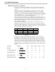
A voltage-sensing circuit attenuates the amplifier's output voltage by a factor of 22. This
voltage is then fed-back into the Tach input. Setting the voltage-gain then is similar to
setting-up a system with a tachometer.
Notice the similarities between the circuit below, and the one shown above for a
tachometer-feedback system:
REF
INPUTS
R2
R11
TO
PWM
STAGE
SERVO
PREAMP
X0.8
GAIN
-
+
R1
1
22
Vout
Fig. 11
We can now express the voltage gain like this:
()
+×
×=
11
2122
8.0
R
RR
Vref
Vout
Fig. 12
And rearrange to solve for R11 like this:
R
RR V
V
ref
out
11
17 6 1 2
=
×+ ×.( )
Fig. 13
This equation holds true when R31, the voltage-gain trimpot is set fully CCW (counter-
clockwise). As this pot is turned CW (clockwise) the gain will increase to a value limited
only by the gain of the servo preamplifier stage. The best procedure is to set the gain by
the equation above to a value slightly less than the ideal, using stock resistor values.
Then adjust R31 for the exact gain desired, which must always be slightly greater than
the gain set by the equation.
Changing R2 from 40K to 0 ohms (jumper), and R11 from 50K to 180K will result in a
voltage gain of 0.98, as R1 = 10K, which is the minimum value that you should use for
the (R1+R2) equivalent. Adjusting R31 will now set the gain to 1.00 which means that a
reference voltage of 10V will drive the outputs to 10V.
Suppose that you are operating at a nominal 75V buss, and want to control a 60V swing
at the outputs with a 10V reference signal. The voltage gain would be 60/10 or 6.0.
Use these values in the equation above and see that the new value of R11 would be
29.3K ohms. By using a 33K ohm value, the trimpot R31 on the MB4 can then be used
to adjust the gain upwards slightly to an exact 6.0.
R
KV
V
R
KV
V
R Kohms
ref
out
11
17 6 10
11
17 6 10 10
60
11 29 3
=
××
=
××
=
.
.
.
Fig. 14