
User`s guide


300 SERIES USER GUIDE
8
Basic Amplifier:
Current-Mode
WITH Tachometer
1. Setup J17 header components for high gain, tachometer mode (see p.3)
2. Connect DC power supply to amplifier +HV and GND. Check voltage to see that is
within the amplifiers' rating.
3. Ground amplifier to chassis at GND pin DD.
4. Connect motor or load between OUT+ and OUT-. Do not ground load!
5. Connect reference voltage source to REF+ and REF- inputs.
6. Connect Tachometer between tach input and signal ground.
7. Ground ENABLE,POS ENABLE, NEG ENABLE to amplifier logic ground.
8. Set FEEDBACK pot to full CW.
9. Set
VREF
to 0V
10. Turn power on.
11. Does the motor run away?:
YES: remove power, reverse tachometer leads
NO: continue
12. Check for green LED indicating Normal operation.
13. Adjust BALANCE trimpot for 0.0V between OUT+ and OUT-
14. Momentarily increase Reference voltage (±10V max).
15. Check motor direction: is it OK?
YES: continue
NO: remove power, reverse connections to Ref+ and Ref-.
16. Set Reference voltage to maximum value (+/-10V)
17. Check load current at CURRENT MONITOR output
18. Adjust CURRENT LIMIT trimpot for desired maximum current.
19. Set Reference voltage to zero, turn feedback trimpot CCW until oscillation begins
(audible squeal or noise). Back-off two turns CW or until oscillation stops.
20. Apply step or square-wave signal to Ref-inputs, adjust FEEDBACK CCW for best
response with no oscillation.
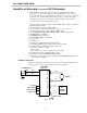
Amplifier Connections
Single-letter terminals are on the brown 22-pin connector. Double-letter terminals are on
the orange 4-pin connector.
15
16
17
7
+HV
GND
+
-
DC
OUT+
OUT-
MOTOR
AA
DD
CHASSIS GND
1
2
AMPLIFIER
BB
CC
REF+
REF-
ENABLE
POS ENABLE
NEG ENABLE
LOGIC GND
13
3
TACH
+
-
+
-
CONTROLLER
POWER
SUPPLY
22-Pin
4-Pin
Fig. 2