
User guide


Page 41
ServoTube 25/38 module User Guide
Appendices
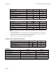
FORCER ELECTRICAL SPECIFICATIONS (CONTINUED)
FORCER TYPE
3804 3806 3808 3810
units
S
(1)
P
(1)
S
(1)
P
(1)
S
(1)
P
(1)
S
(1)
P
(1)
Peak force @ 25
o
C ambient for 1 sec 744 372 1116 558 1488 744 1860 930 N
Peak current @ 25
o
C ambient for 1 sec 20 Apk
With 25 x 25 x2.5cm heatsink plate
Continuous stall force @ 25
o
C ambient
(2)
137.3 186.9 232.1 276.2 N
Continuous stall current @ 25
o
C ambi-
ent
2.61 5.23 2.37 4.74 2.20 4.41 2.10 4.20 Arms
3.69 7.39 3.35 6.71 3.12 6.23 2.97 5.94 Apk
Without heatsink plate
Continuous stall force @ 25
o
C ambient
(2)
120.1 168.2 212.7 255.0 N
Continuous stall current @ 25
o
C ambi-
ent
2.28 4.57 2.13 4.27 2.02 4.04 1.94 3.88 Arms
3.23 6.46 3.01 6.03 2.86 5.72 2.74 5.49 Apk
Force constant (sine commutation) 52.6 26.3 78.9 39.4 105.2 52.6 131.5 65.7 N/Arms
37.2 18.6 55.8 27.9 74.4 37.2 93.0 46.5 N/Apk
Back EMF constant (phase to phase) 43.0 21.5 64.4 32.2 85.9 42.9 107.4 53.7 Vpk/m/s
Fundamental forcer constant 14.54 17.80 20.56 22.99 N/√W
Eddy current loss 3.7 3.7 3.7 3.7 N/m/s
Sleeve cogging force 7.3 4.2 8.3 5.6 +/-N
Resistance @ 25
o
C (phase to phase) 6.77 1.69 10.16 2.54 13.54 3.38 16.93 4.23 Ohm
Resistance @ 100
o
C (phase to phase) 8.73 2.18 13.10 3.27 17.45 4.36 21.82 5.45 Ohm
Inductance @ 1kHz (phase to phase) 8.52 2.13 12.78 3.19 17.04 4.26 21.30 5.32 mH
Electrical time constant 1.26 ms
Maximum working voltage 380 V d.c.
Pole pitch (one electrical cycle) 71.2 mm
Peak acceleration
(3)
243 121 275 137 294 147 307 153 m/s
2
Maximum speed
(4)
5.9 8.7 4.2 7.1 3.3 5.8 2.6 4.9 m/s
Notes: -
(1)
S=series forcer phases, P=parallel forcer phases
(2)
Reduce continuous stall force to 89% at 40
o
C ambient
(3)
Based on a moving forcer with to payload
(4)
Based on a moving forcer with triangular move over maximum stroke and no payload