
User guide


Page 29
ServoTube 25/38 Module User Guide
Chapter 3
Maintenance
FORCER REPLACEMENT
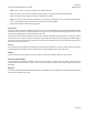
When the forcer is removed from the module, it will have the following items attached that will need to be transferred
to the replacement forcer.
Bearing carriage(s). There will be 1 or 2 bearing carriages depending on the particular version.•
The encoder readhead bracket tted with the encoder readhead.•
The limit switch actuator if tted.•
The drag chain upper mounting bracket.•
The pod base however, is an integral part of the forcer and is programmed for the forcer it is attached to. The
replacement forcer will have its own specically programmed pod base.
Removal
Remove the bellows (if applicable) as described on page 24. •
Remove the thrust rod as described on page 26.•
Follow the procedure for Cable Replacement described on page 22 and free the cables from the drag chain, •
but do not remove the cables from the pod. Additionally remove the drag chain link that secures the drag
chain to the upper mounting bracket which is tted to the forcer.
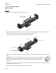
SM25 and XM38
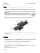
For the SM25 or XM38, see Figure 3.16. Remove the three M6 xings securing a thrust rod support to the •
backing bar and slide the thrust rod support out of the backing bar, see Figure 3.17.
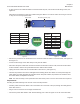
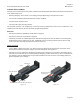
Remove the forcer by sliding it off the bearing rail taking care to keep the forcer square to the bearing rail so •
that balls are not lost from the re-circulating bearing carriage(s). If balls do fall out they can be re-inserted into
the carriages. Push the ball bearings using a small screwdriver into the end of the re-circulating path at the
plastic end plates on the carriage.
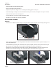
Figure 3.17
Move forcer off end
of bearing rail
Forcer
Forcer
Remove these screws and thrust rod support
Bearing rail
Thrust rod support
Backing bar
Figure 3.16