
User guide


ServoTube 25/38 Module User Guide
Chapter 3
Maintenance
Page 26
THRUST ROD REPLACEMENT
SM25 and XM38
Removal
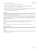
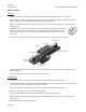
Move the forcer to the centre of the module, Figure 3.12.•
Place spacers around or under the thrust rod to prevent it coming into contact with the bearing rail or other •
ferrous material. Foam pipe insulation or wooden blocks are ideal for this.
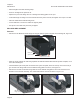
Loosen the two M10 bolts on each of the thrust rod end supports. •
Note. When an SM2504 is tted with an optional encoder, one of the thrust rod supports has only one M10
bolt).
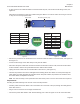
Important. There is a serial number label on one end of the thrust rod. Record the end that
has the serial number and its orientation. It is important when replacing the thrust rod this
parameter is maintained. The serial number should be horizontal and read left to right as
shown right.
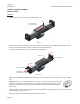
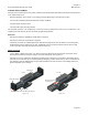
Carefully slide the thrust rod out through the thrust rod supports and forcer (Figure 3.13) until it is clear of the •
module assembly, see Figure 3.14.
Store the thrust rod in a safe place away from ferrous material.•
Thrust rod support
Thrust rod support
Thrust rod
Loosen
Loosen
Carefully slide
thrust rod out of module
Forcer
Position forcer to
centre of module
Figure 3.12
Figure 3.13