
User guide


Page 23
ServoTube 25/38 Module User Guide
Chapter 3
Maintenance
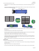
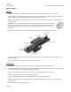
To gain access to the cable termination connectors inside the pod, unscrew the four M3 xing screws, see •
Figure 3.5.
Note that the pod lid xing screws are of different lengths. Make a record from where each xing is removed
so they can be correctly replaced later.
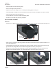
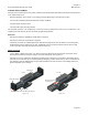
Remove the pod lid from the termination box to reveal the cable termination connectors inside, see Figure 3.6 •
and Figure 3.7.
Loosen the two xings on the cable clamp to fully free the cables.•
Disconnect the power cable from the PCB mounted screw terminal connector TB1, and unscrew the earth/•
screen terminal to remove the eyelet fastened to the cable screen terminal.
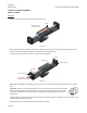
Unplug the sensor cable from the vertical PCB at connector PL1 (see Figure 3.7).•
Unscrew the pressure nut from the cable gland and carefully pull the two cables out of the pod through the •
cable gland. The cable assembly will comprise sensor and power cables, the pressure nut and at the other
end of the cables, the amplier connectors.
Note. The cable assembly is the replacement item when either power or sensor cable needs to be replaced.
Replacement
Re-tting the cable assembly is the reverse of the removal procedure.
Feed the power and sensor cables to be connected to the connectors in the pod, through the cable gland to •
reach TB1 and PL1.
Plug PL1 into its connector on the edge-mounted PCB.•
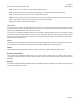
Connect the power cable leads to TB1 and the earthing point. Refer to Figure 3.6 for the connection table.•
PL1
PIN
NUMBER
FUNCTION
1 +SIN
2 -SIN
3 +COS
4 -COS
5 +5Vd.c.
6 0V
7 +TH (Thermistor)
8 -TH (Thermistor)
Figure 3.7
TB1
PIN NUMBER FUNCTION
1 Phase U
2 Phase V
3 Phase W
Chassis Earth/Screen
Figure 3.6
Figure 3.5
Power cable
Sensor cable
M3 lid fixing screws (4 off)
Pod lid