
Operation Manual
user instructions TWIN80C_EN
3
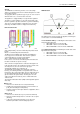
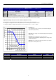
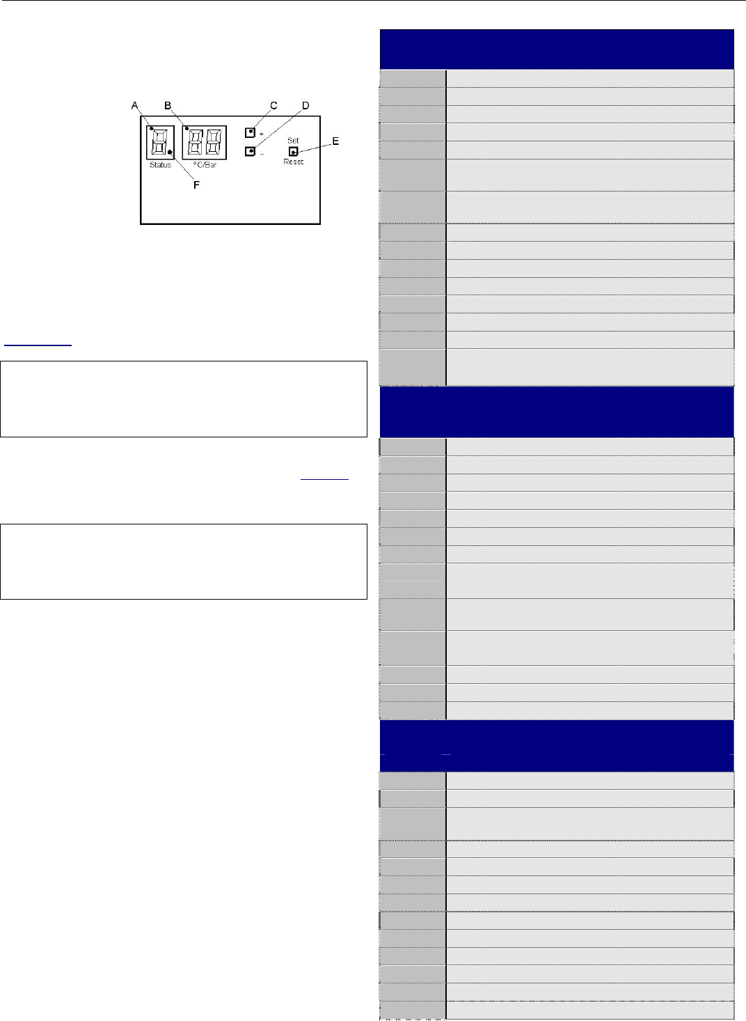
Display
To be able to read the codes of the, open the cover in front of
the appliance.
A = Status
B = Reading
C = “+ button”
D = “- button”
E = Set / Reset
F = Flame
The left 7-segment LED shows the status or the menu step.
The two right 7-segment LED's show the temperature, the
pressure or the parameter value.
What is a functional blocking?
During blocking operation, the display status shows a
continuous
indication. The regulation blocks the burner till
blocking conditions are within certain requirements.
Most blocking actions restore automatically in time. Some
blocking operations need a reset of the 230V supply power or an
action manually.
Note that each blocking operation will stay at least with 3
minutes anti-cycling time.
What is a functional lock-out?
During lock-out operation, the display status shows a flashing
indication.
Pump runs over the heating circuit (max 24 hr).
Fan post rinses for 1 minute at 2700 rpm (some lock-outs)
Most lock-out operations can be restored by pressing the
‘Set/Reset’ button. It is advised to use this button not more than
3 times in a row. Ask your installer for help.
Note that some lock-out operations need a reset of the 230V
supply power.
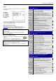
Status indication during normal operation
Display Description
- Initialisation after restoration of supply power
U Reversed neutral and line
O No heat demand, stand-by
C Central heating heat demand, burner off
C. Central heating heat demand, burner on
P/C.
(Central heating) heat demand, low load water
pressure
A/C.
(Central heating) heat demand, low load chimney
temperature
c Central heating pump post-running
b HWS burner off/ pump post running
b. HWS burner on
P/b. HWS, low load by water pressure
A/b. HWS, low load by chimney temperature
O Frost protection burner off pump running 8C
o. Frost protection burner on 3C
C
FLASHING
Chimney sweeper function (temp display
max/min/ionisation)
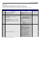
Status indication during “blocking” mode
(intermittent “L” for master and “r” for slave)
Display Description
1 Flow sensor open circuit
1. Flow sensor short circuit
2 Return sensor open circuit
2. Return sensor short circuited
4 Flue gas sensor open circuit
A Flue gas temperature > 80°C
H Flow sensor > 105°C while the burner was off
J Blocking flow temperature
(3 minutes anti-cycling time)
P
Pump test / Start function blocking / Water
pressure
nc Electronics interruption
(manual reset by interruption of electrical supply)
E No slave connected
b/r HWS right unit
9 Flow / Return temperature to high
Status indication of ”lock-out” mode (flashing)
(intermittent “L” for master and “r” for slave)
Display Description
1 Boiler does not pass start temperature test
2 Too many restarts
3
Internal regulation fault / A/D conversion fault /
external sensor fault /Too many restarts
4
5 Fan error
6
7 Gas valve error
8 Flame detected with closed gas valve
A Flue gas temperature > 95°C
E Internal interlock fault
H Flow sensor > 105°C with burner on
F Too many ignition attempts during
O Gas valve connection error