
Instruction manual


P84662J Page 19 of 28
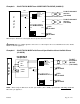
Example 13: WHEELOCK SYNC MODE without Audible Silence (CLASS A)
POWERPATH
OUT4
OUT2
OUT3
-
+
OUT1
-
+
-
+
IN2
-
+
IN1
C
P
F
A
RET1
-
+
TO NEXT APPLIANCE
OR RETURN
TO FACP
(CLASS "A")
OR EOLR
-
RET2
+
-
+
+
-
OUT1-4
IN>OUT SYNC
WHEELOCK SYNC
TEMPORAL
INPUT SELECT
1
2
3
4
ON
1
2
3
4
ON
SW7
• This mode will only synchronize Wheelock horns, horn strobes, and strobes with the synchronization capability.
• If only strobes are connected to the POWERPATH outputs, the initiating input to IN2 is not required.
• When synchronized horns are used on the two wire output of the POWERPATH, IN2 must be connected as
shown or the horns will not operate.
Example 14: WHEELOCK SYNC MODE with Audible Silence (CLASS A)
POWERPATH
OUT4
OUT2
OUT3
+
-
-
+
OUT1
-
+
-
RET2
+
IN2
+
-
IN1
+
-
AUDIBLE SILENCE
+
RET1
-
A
F
P
C
OR EOLR
OR RETURN
TO FACP
(CLASS "A")
TO NEXT APPLIANCE
TO NEXT APPLIANCE
(CLASS "A")
TO FACP
OR RETURN
OR EOLR
+
-
OUT1-4
IN>OUT SYNC
WHEELOCK SYNC
TEMPORAL
INPUT SELECT
1
2
3
4
ON
1
2
3
4
ON
SW7
• This mode will only synchronize Wheelock horns, horn strobes, and strobes with the synchronization capability.
COMBINATION CLASS “A” AND CLASS “B” HOOKUP
The PS-24-8MC POWERPATH can be configured to have one Class “A” (3.0 Amps) and two Class “B” (3.0 Amps
each circuit) outputs at the same time, with a maximum 8 Amps total for the unit. This is done by Switch SW7
position 1 & 2. NOTE: When SW7 position 1 is ON, OUTPUTS 1 and 3 are the Class “A” circuit. When SW7
position 2 is ON, OUTPUTS 2 and 4 are the Class “A” circuit.
COMBINATION OF MODES
• In Class “B” configuration, each output can be set to an independent mode as desired.
• In Class “B”, IN1 or IN2 can be selected to activate any of the outputs desired.
• In Class “A”, OUTPUT DIP Switches must be set identically for each Class “A” output.