
Installation Manual

•
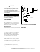
Attach ground lead of the arrester (connected to the base
of the arrester) to the system ground with 4 to 8 ft-lbs
torque.
•
Attach a grounded drain wire to the elbow arrester drain
wire tab. This ensures that the arrester is grounded if the
end cap is separated during a pressure relief event.
•
Lubricate the arrester interface with the lubricant
supplied.
•
Use a clampstick to remove the mating connector from
the apparatus bushing. Install mating connector on a
parking stand bushing.
•
Verify ground lead attachment.
•
Grasp pulling the eye of the arrester firmly using a
clampstick. Position the tip of the arrester probe just into
the nose of the loadbreak bushing. Position the arrester
so that its grounded end points downward or at an
adjacent ground plane.
•
Thrust the arrester firmly onto the bushing.
WARNING
The operator should always use personal protective
equipment (insulated gloves, clampstick, and eye
protection) whenever operating the elbow. The
operator should always be in the best possible
operating position, providing firm footing and
enabling a secure grasp of the clampstick, while
maintaining positive control of the elbow before,
during, and immediately after operation. If there
is any question regarding the operator's operating
position, de-energize the elbow before operation.
The operator should not be looking directly at the
connector during the moment of circuit interruption
or connection. Failure to comply could result in death
or serious injury.
3
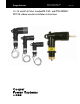
15, 25, and 35 kV class standard M.O.V.E. and
POSI-BREAK M.O.V.E. elbow arrester installation instructions S235-55-1 September 2013 www.cooperpower.com