
Installation Manual
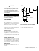

Installation procedure
Application
The M.O.V.E. Elbow Arrester should be installed only on
systems where the power frequency voltage at the arrester
does not exceed the maximum continuous operating
voltage. (MCOV) values published. See Table 2.
All Eaton's Cooper Power Systems M.O.V.E. Elbow
Arresters must be installed or removed from an energized
bushing with a clampstick.
ote:N Because the M.O.V.E. Elbow Arrester has a
completely grounded case, it may be installed
anywhere within the apparatus primary
compartment. Determine the space requirements
of the M.O.V.E. Elbow Arrester and ground lead
before installation so that they do not restrict
the installation, operation or removal of other
devices.
Installation on an energized or de-energized system
ote:N Verify the M.O.V.E. Elbow Arrester has the proper
interface and voltage rating for the application.
ote:N When the M.O.V.E. Elbow Arrester is installed on
an energized system, it must be positioned so
that its grounded end points downward or at the
adjacent ground plane. A clampstick should be
utilized when installing a M.O.V.E. Elbow Arrester
on an energized system.
ote:N Excessive force on the ground lead may cause the
metal cap to separate from the arrester housing.
Never handle the arrester by the attached ground
lead.
ote:N The nut attaching the ground lead to the
threaded stud on the metal cap is factory
installed to the proper torque value. Do not
remove or retighten. Over torquing of the ground
lead nut may cause the metal cap to separate
from the arrester housing.
Table 2. Recommended M.O.V.E. Arrester Applications
Nominal Circuit
Voltage (kV)
Maximum
Voltage (kV)
Duty Cycle (MCOV Ratings) (kV)
4-Wire Wye;
Multi-grounded Neutral
3-Wire Wye; Solidly Grounded
Neutral 30 minute
1
Delta and Ungrounded
Wye
2
2.4 2.54 — — 3 (2.55)
4.15 Y/2.4 4.4 Y/2.54 3 (2.55) 6 (5.1) —
4.16 4.4 — — 6 (5.1)
4.8 5.08 — — 6 (5.1)
6.9 7.26 — — 9 (7.65)
8.32 Y/4.8 8.8 Y/5.08 6 (5.1) 9 (7.65) —
12.0 Y/6.93 12.7 Y/7.33 9 (7.65) 12 (10.2) —
12.47 Y/7.2 13.2 Y/7.62 9 (7.65) 15 (12.7) —
13.2 Y/7.62 13.97 Y/8.07 10 (8.4) 15 (12.7) —
13.8 Y/7.97 14.52 Y/8.38 10 (8.4) 15 (12.7) —
13.8 14.52 — — 18 (15.2)
20.78 Y/12.0 22.0 Y/12.7 15 (12.7) 21 (17.0) —
1. Line-to-ground fault duration not to exceed 30 minutes. For longer durations, contact the factory for proper rating.
2. Use for high impedance grounded systems also.
Table 1. Electrical Apparatus Specifiers Catalog
Section Number Reference
M.O.V.E. Arrester Design Catalog Section
Standard M.O.V.E. 235-65
POSI-BREAK M.O.V.E. 235-97
CAUTION
High Voltage. Do not install an arrester if the voltage or MCOV data
listed on the arrester label are not exactly the same as that listed
on the carton label. Do not install the arrester if the system line-to-
ground voltage exceeds the MCOV rating on the arrester. Failure to
comply may result in minor or moderate injury.
WARNING
High Voltage. All associated apparatus must be de-energized during
hands-on installation or maintenance. Failure to comply may result
in death or serious personal injury.
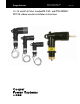
2 15, 25, and 35 kV class standard M.O.V.E. and
POSI-BREAK M.O.V.E. elbow arrester installation instructions S235-55-1 September 2013 www.cooperpower.com