SURE-LITES LIFEWAY II SERIES MICRO MODULAR INVERTER SERIES 500W – 2,000W Users Manual
CAUTION READ ENTIRE MANUAL AND REVIEW ALL DOCUMENTATION BEFORE ATTEMPTING SYSTEM INSTALLATION FOR SERVICE OR INSTALLATION INFORMATION: TELEPHONE: (610) 868-5400 (24 HR. HOTLINE) FAX: (610) 954-8227 FOR YOUR PROTECTION PLEASE COMPLETE AND RETURN WARRANTY REGISTRATION CARD IMMEDIATELY.
This unit contains LETHAL VOLTAGES. All repairs and service should be performed by AUTHORIZED SERVICE PERSONNEL ONLY! There are NO USER SERVICEABLE PARTS inside this unit. IMPORTANT SAFEGUARDS When using electrical equipment, you should always follow basic safety precautions, including the following: 1. READ AND FOLLOW ALL SAFETY INSTRUCTIONS. 2. Do not install the system outdoors. 3. Do not install near gas or electric heaters or in other high-temperature locations. 4.
User’s Guide An on-site permanent log of the inspection, testing, and maintenance of the emergency electrical power supply system shall be maintained in accordance with the Manufacturer's operating manual. The log shall include: The date on which the inspection, testing, and maintenance exercise was carried out. The name of the person(s) who performed the inspection, testing, and maintenance. A note of any unsatisfactory condition observed or discovered, and the steps taken to correct the condition.
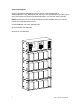
CHAPTER1 INTRODUCTION Keep this manual and the System Installation Guide in the folder mounted inside the unit. This unit is a microprocessor controlled PWM (Pulse Width Modulated) pure sine wave based DC to AC power inverter utilizing MOSFET technology. It integrates a fully automatic 3-rate battery charger, a solid-state transfer system, control circuitry, self testing and recording digital meter display, and maintenance free sealed lead calcium type batteries.
Service and Support We are committed to outstanding customer service. A service technician is available 24 hours a day, 365 days a year. Service is also available 24 hours a day to give you access to technical notes and product information. You can also visit our web site. NOTE: Please have your unit’s Serial and Model numbers available when you call; this number is located behind the left door.
CHAPTER2 Environment Make sure the environment is a clean, cool, dry place with normal ventilation. Storage Temperature Store the batteries (in the system or battery cabinet) at -18 to 40°C (0 to 104°F). Batteries have a longer shelf life if they are stored below 25°C (77°F). Keep stored batteries fully charged. Recharge the batteries every 90–120 days. The system or battery cabinet without batteries may be stored at -20 to 70°C (-4 to 158°F).
CHAPTER3 Startup and Shutdown Procedure Refer to the Installation Manual to secure the unit and install AC and DC wiring. STARTUP PROCEDURE For the initial startup of the system, follow the instructions in the Startup and Warranty Validation Form. Failure to do so will void warranty. CAUTION: HAZARDOUS VOLTAGES – ONLY QUALFIED SERVICE PERSONNEL SHOULD PERFORM PROCEDURE. 1. Verify that the installation switch located below the front panel is in the OFF position. Verify that AC input is disconnected. 2.
CHAPTER4 OPERATION The following is a description of the status LED's located on the front panel and the internal fan. AC Present When the AC Mains is present, the LED will illuminate. If a power failure was long in duration, or the AC mains was disconnected by some other means (Circuit breaker open) the AC Present LED would not be illuminated.
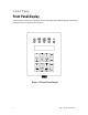
CHAPTER5 Front Panel Display The Front panel consists of a 2 x 20 alpha numeric LCD display with LED Back lighting, 5 Status LED indicators and a 4 x 4 keypad for user interface. Figure 5.
Control Panel Keypads Table 5.1 Keypad Functions Key Name Description Meter (Blue) Control (Red) Program (Black) Pressing this key will activate Meter Functions Pressing this key will activate Control Functions Using this key, you can enter passwords or change parameter values. To enter passwords, press [PROGRAM], enter the password, and press [ENTER]. NOTE: A password must be entered to change parameters. This key records or enters a task you perform using the control panel keys.
Control Functions Control functions are available by pressing "CONTROL" to get to the Control Menu and then pressing the desired function. Table 5.3 Control Functions Function Test Log Event Log Initiate Test Alarm Log Buzzer Silence Keypad Text TEST LOG EVENT LOG TEST ALARM BUZZER • TEST LOG - View the Test Log of the last 75 monthly or Yearly Tests. View the Date, Time, Duration, Output Voltage, Output Current, Temperature and Fault Status. Use the left and right scroll key to change event number.
Table 5.4 Program Functions 12 Parameter Format Factory Default Date Time Monthly Test Date Monthly Test Time Yearly Test Date Yearly Test Time Load Reduction Low VAC Alarm High VAC Alarm Ambient Temp Alarm Near Low Battery MM/DD/YY (Month, Date, Year) HH/MM (Hours, Minutes) DD (Date) HH/MM (Hours, Minutes) MM (Month) HH/MM (Hours, Minutes) AAAA(Amps) VVVV(Volts) VVVV(Volts) DDD(Degrees Centigrade) VVVV(Volts) Current Date Eastern Stand Time th 15 of the Month 5:00 01 8:00 0.0A 1.0V 999.
CHAPTER6 SPECIFICATIONS General Specifications Input Voltage Input Power Walk-in Input Frequency Synchronizing Slew Rate Protection Harmonic Distortion Power Factor Output Voltage Static Voltage Dynamic Voltage Harmonic Distortion Overload Output Frequency Load Power Factor Inverter Overload Protection Battery Type Charger Protection Disconnect Optional Runtimes Environmental General Physical 13 Altitude Operating Temperature Storage Temperature Relative Humidity 120 or 277Vac 1-phase 2-wire +10
CHAPTER7 MAINTENANCE AND SERVICE The Self-testing feature of the inverter ensures that the system is tested at least once per month for 5 minutes and once per year for 90 minutes. If there are any problems with the self-tests, the fault log shall indicate which faults occurred. Please see the fault descriptions and troubleshooting guide. A few simple maintenance operations performed periodically will help ensure many years of trouble free operation.
15 THE NUMBER IN THE CHART INDICATES ORDER IN WHICH PROBLEM S SHOULD BE CHECKED S Inverter System System AC output System System Inverter System Y will not draws noisy, voltage overheats, noisy, jitters or blows M run excessive excessive low smells, transformer staggers battery fuse P during a AC input transformer during a smokes, hum during a (& fuses in T power current hum during utility etc.
RETURN MATERIAL AUTHORIZATION (RMA) POLICY No return material is accepted without written "Return Material Authorization"(RMA). An RMA number is obtainable by contacting the Field Service Department. Every effort will be made to correct problems over the phone before a RMA is granted or a service trip made. Cooperation will save both time and expense for customer and manufacturer. If it is deemed necessary to return material, the RMA number must appear on shipping labels, packing slips, and bills of lading.
LIMITED WARRANTY The parts and on-site labor for the electronics portion of this equipment are warranted against defects in workmanship and material for a period of one year from time of shipment, but in no case will this warranty be valid if installation of equipment is not accomplished within 180 days from date of shipment.