XC/XPP/XST Mechanical Force Gauges User’s Guide www.cooperinstruments.
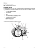
MODELS XC – with compression calibration XST – with tension calibration XPP - with compression/tension calibration PRINCIPAL PARTS For easy identification of Force Gauge parts*, the following illustration has been prepared. Correspondence with our Service Department should refer to this illustration, and a rough pencil sketch of your particular setup will be helpful. 1. 2. 3. 4. 5. 6. 7. 8. 9. 10. 11. 12.
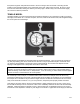
OPERATIONAL DATA IMPORTANT! When adjusting bezel-locking screw, #10, only tighten as much as is necessary to hold bezel in proper position. DO NOT OVERTIGHTEN, as this will distort the thin housing of the dial indicator gauge; affect the smooth action of the movement and produce false readings! Your Force Gauge is ready to go to work for you without any special assembly. Upon removing it from the storage case, it is only necessary to check the zero setting.
then pass through this solid path without harm to the Force Gauge. Note the method of mounting the dial indicator to the supporting bracket on the reverse side of the case. Allen screws are used. Be sure to check these screws at intervals, making sure that they are always tight. Vibration may in time loosen them slightly, and it is best to take this precaution.
WARRANTY REPAIR POLICY Limited Warranty On Products Any Cooper Instruments product which, under normal operating conditions, proves defective in material or in workmanship within one year of the date of shipment by Cooper will be repaired or replaced free of charge provided that a return material authorization is obtained from Cooper and the defective product is sent, transportation charges prepaid, with notice of the defect, and it is established that the product has been properly installed, maintained, an