Series TT03 DIGITAL TORQUE GAUGES User’s Guide
Series TT03 Digital Torque Gauges User’s Guide Thank you… Thank you for purchasing a Mark-10 Series TT03 digital torque gauge, designed for handheld or test stand use. With proper usage, we are confident that you will get many years of great service with this product. Mark-10 instruments are ruggedly built for many years of service in laboratory and industrial environments. This User’s Guide provides setup, safety, and operation instructions. Dimensions and specifications are also provided.
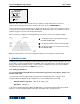
Series TT03 Digital Torque Gauges User’s Guide 1 OVERVIEW 1.1 List of included items Qty. 1 1 1 1 1 1 Part No. 12-1049 08-1022 08-1026 09-1165 - Description Carrying Case AC adapter body with US, EU, or UK prong Battery (inside the gauge) Certificate of calibration USB cable Resource CD (USB driver, user’s guides, MESURTM Lite software, MESURTMgauge DEMO software, User’s Guide) 1.2 Safety / Proper Usage Caution! Note the torque gauge’s capacity before use and ensure that the capacity is not exceeded.
Series TT03 Digital Torque Gauges User’s Guide 2 POWER The TT03 is powered either by an 8.4V NiMH rechargeable battery or by an AC adapter. Since these batteries are subject to self discharge, it may be necessary to recharge the unit after a prolonged period of storage. Plug the accompanying charger into the AC outlet and insert the charger plug into the receptacle on the gauge (refer to the illustration below). The battery will fully charge in approximately 8 hours.
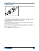
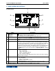
Series TT03 Digital Torque Gauges User’s Guide 3 MECHANICAL SETUP Fig. 3.1 Proper axial loading of Series TT03 torque gauge. 3.1 Proper alignment Load must be applied axially with respect to the sensor, as shown in Figure 3.1. If attachments are used, ensure that the sample is acted upon axially with respect to the instrument. Side loading or off-center loading can damage the instrument, whether power is turned on or off. 3.
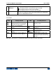
Series TT03 Digital Torque Gauges User’s Guide 4 HOME SCREEN AND CONTROLS 4.1 Home Screen 1 9 2 8 3 4 7 6 No. 1 2 Name Measurement direction indicator Peaks 3 Primary reading 4 Load bar 5 Units 6 Mode 7 Battery / AC adapter indicator 5 Description – indicates clockwise direction – indicates counter-clockwise direction These indicators are used throughout the display and menu. The maximum measured clockwise and counter-clockwise readings.
Series TT03 Digital Torque Gauges 8 High / low limit indicators 9 Set points User’s Guide Correspond to the programmed set points. Indicator definitions are as follows: – the displayed value is greater than the upper load limit – the displayed value is between the load limits – the displayed value is less than the lower load limit The programmed load limit values. Typically used for pass/fail type testing.
Series TT03 Digital Torque Gauges User’s Guide 4.3 Menu navigation basics Most of the gauge’s various functions and parameters are configured through the main menu. To access the menu press MENU. Use the UP and DOWN keys to scroll through the items. The current selection is denoted with clear text over a dark background. Press ENTER to select a menu item, then use UP and DOWN again to scroll through the sub-menus. Press ENTER again to select the sub-menu item.
Series TT03 Digital Torque Gauges User’s Guide 6 CHANGING THE UNITS The TT03 can display three different measurement units, depending on the model. To change the unit, select Units from the menu. The display will list the available units, for example: UNITS * lbFin kgFmm Ncm The gauge will always power on with the unit selected. 7 DIGITAL FILTERS Digital filters are provided to help smooth out the readings in situations where there is mechanical interference in the work area or test sample.
Series TT03 Digital Torque Gauges User’s Guide SET POINTS Upper Disabled * Upper Enabled 5.00 Lower Disabled * Lower Enabled 3.50 Either one, two, or none of the set points may be enabled. To toggle between the tension and compression (or clockwise and counter-clockwise) directions, press the DIRECTION key. If two set points have been enabled, they are displayed in the upper left corner of the display. If only one set point has been enabled, the word “OFF” will appear in place of the value.
Series TT03 Digital Torque Gauges User’s Guide or Click “Install”. 3. The next screen appears as follows: Click “Continue Anyway”. 4. After installation completes the following screen may appear in non-Windows 7 operating systems. Restart the computer before connecting a Mark-10 USB device. 5. After Windows as restarted, plug in the device. The following will occur: Windows 7 Operating Systems – When the Mark-10 USB device has been plugged into a USB port, the driver will automatically be found.
Series TT03 Digital Torque Gauges User’s Guide Select “No, not this time”, then click “Next”. 6. The next screen appears as follows: Select “Install the software automatically (Recommended)”, then click “Next”. 7. The next screen appears as follows: Click “Continue Anyway”.
Series TT03 Digital Torque Gauges User’s Guide 8. The next, and final, screen appears as follows: Click “Finish”. The Mark-10 USB device is now installed and ready to use. The COM port number assigned by Windows may be identified in Device Manager, or in the communication application being used, such as MESURgauge or HyperTerminal. 9.2 Communication Settings To set up communication settings, select USB Settings from the menu.
Series TT03 Digital Torque Gauges User’s Guide 10.2 Calibration Procedure 1. Select Calibration from the menu. The display will appear as follows: CALIBRATION ENTER # CAL POINTS (1 TO 10) CLOCKWISE: 5 COUNTER-CLOCKWISE: 5 The sensor can be calibrated at up to 10 points in each direction. Enter the number of calibration points for each direction. At least one point must be selected for each direction. Note: To achieve the accuracy specification of ±0.
Series TT03 Digital Torque Gauges User’s Guide CALIBRATION OFFSET CALIBRATION OFFSET Sen.Offset Adj.Passed Ana.Offset Adj.Passed Sen.Offset Adj.Failed Ana.Offset Adj.Failed If failed: 5. The following screen appears after the offsets have been calculated: CALIBRATION CLOCKWISE Attach necessary weight fixtures. THEN PRESS ENTER Keep the sensor in a vertical position, as explained in Section 10.1. Attach weight fixtures (brackets, hooks, etc), as required.
Series TT03 Digital Torque Gauges User’s Guide Remove the torque applied in Step 7, leave the fixtures in place, then press ZERO. 9. The display will appear as follows: CALIBRATION CLOCKWISE APPLY LOAD 1 OF 5 ENTER LOAD: 10.000 LBFIN THEN PRESS ENTER Use the UP and DOWN keys to adjust the torque value as required. The torque values default to even increments, as indicated by the previously entered number of data points described in Step 1. Then press ENTER.
Series TT03 Digital Torque Gauges User’s Guide LOAD NOT STABLE PLEASE TRY AGAIN Ensure that the load is not swinging, oscillating, or vibrating in any manner. Then try again. CALIBRATION CLOCKWISE LOAD TOO LOW PLEASE TRY AGAIN The calibration load does not match the set value. CALIBRATION COUNTER-CLOCKWISE LOAD TOO CLOSE TO PREVIOUS PLEASE TRY AGAIN The entered calibration point is too close to the previous point. 11 OTHER SETTINGS 11.
Series TT03 Digital Torque Gauges User’s Guide 11.2 Backlight Several initial settings are available upon powering on the gauge. To access these settings, select Backlight from the menu. The display will appear as follows: BACKLIGHT Off On * Auto Set Minutes 1 Select Off for the backlight to be off upon powering on the gauge. Select On for the backlight to be on upon powering on the gauge.
Series TT03 Digital Torque Gauges User’s Guide 11.5 Initial Mode This section is used to configure the initial mode upon powering on the gauge. To access this parameter, select Initial Mode from the menu. The screen will display the available modes. An example is as follows: INITIAL MODE * Real Time Peak Clockwise Peak Counter-clockwise The default value is Real Time. 11.
Series TT03 Digital Torque Gauges User’s Guide 12.
Series TT03 Digital Torque Gauges User’s Guide NOTES: 20
Series TT03 Digital Torque Gauges User’s Guide Mark-10 Corporation has been an innovator in the force and torque measurement fields since 1979. We strive to achieve 100% customer satisfaction through excellence in product design, manufacturing and customer support. In addition to our standard line of products we can provide modifications and custom designs for OEM applications. Our engineering team is eager to satisfy any special requirements.