
Instruction Manual

CF 182 13 32-1117 1010
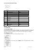
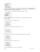
9.6 I/O Connector Pin Diagram (female)
Pin No. Description Input / Output
1 Signal Ground ---
2 Tension Overload Output
3 RS-232 Receive Input
4 RS-232 Transmit Output
5 +12V DC Output
6 Analog Output Output
7 Compression Overload Output
8 Mitutoyo Clock
Output Bit 2
Output
9 Mitutoyo Data
Output Bit 0
Output
10 Mitutoyo Request
Input Bit 3
Input
11 “Under” Set Point Output
12 “Over” Set Point Output
13 “Within” Set Point Output
14 External Trigger Input
15 Mitutoyo Ready
Output Bit 1
Output
10 CALIBRATION
10.1 Initial Physical Setup
The gauge should be mounted vertically to a test stand or fixture rugged enough to withstand a load equal to
the full capacity of the instrument. Certified deadweights or master load cells should be used, along with
appropriate mounting brackets and fixtures. Caution should be taken while handling such equipment.
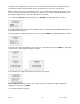
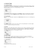
10.2 Calibration Procedure
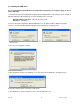
1. Select Calibration from the menu. The display will appear as follows:
16
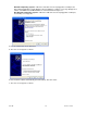
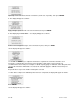
2. Press DIRECTION to invert the display, if desired. ENTER to continue. The display will appear as follows: