Users Guide Series 4 Digital Force Gages www.cooperinstruments.
This page intentionally blank.
Table of Contents 1 OVERVIEW......................................................................................................................................1 2 POWER .............................................................................................................................................2 43 MECHANICAL SETUP .................................................................................................................3 4 HOME SCREEN AND CONTROLS ..................................
Thank you for purchasing a Series 4 digital force gauge, designed for tension and compression force testing applications from 0.12 lb to 500 lb (0.5 N to 2,500 N) full scale. The Series 4 is an essential component of a force testing system, typically also comprising a test stand, grips, and data collection software. With proper usage, we are confident that you will get many years of great service with this product.
The following safety checks and procedures should be performed before and during operation: 1. Never operate the gauge if there is any visible damage to the AC adapter or the gauge itself. 2. Ensure that the gauge is kept away from water or any other electrically conductive liquids at all times. 3. The gauge should be serviced by a trained technician only. AC power must be disconnected and the gauge must be powered off before the housing is opened. 4.
43 MECHANICAL SETUP 3.1 Loading shaft orientation In order to accommodate a variety of testing requirements, the orientation of the loading shaft may be set up in either of the two positions shown below. In order to change the loading shaft orientation, loosen the two captive screws on the back side of the housing, separate the two housing halves, rotate one half 180 degrees, and reassemble. Contact between the two halves is made by the spring pins and contact pads on the printed circuit boards. 3.
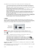
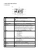
4 HOME SCREEN AND CONTROLS 4.1 Home Screen No. 1 Name Measurement direction 2 Peaks 3 Primary reading 4 Load bar 5 Units 6 Mode 7 Number of stored data points Battery / AC adapter indicator 8 9 High / low limit indicators CF 182 Description - indicates a compression (push) direction - indicates a tension (pull) direction These indicators are used throughout the display and menu. The maximum measured compression and tension readings.
10 – the displayed value is greater than the upper force limit – the displayed value is between the limits – the displayed value is less than the lower force limit The programmed force limits. Typically used for pass/fail type testing. 1, 2, or no indicators may be present, depending on the configuration shown in the Set Points menu item. Set points 4.2 Controls Primary Label Primary Function Secondary Label Secondary Function Powers the gauge on and off.
Refer to the following sections for details about setting up particular functions and parameters. 5 OPERATING MODES Caution! In any operating mode, if the capacity of the instrument has been exceeded by more than 110%, the display will show “OVER” to indicate an overload. A continuous audible tone will be sounded until the MENU key has been pressed or the load has been reduced to a safe level. Three operating modes are possible with Series 4 gauges.
or alarm indication in process control applications. Two limits, high and low, are specified and stored in the non-volatile memory of the instrument and the primary reading is compared to these limits. The results of the comparisons are indicated through the three outputs provided on the 15-pin connector, thus providing “under”, “in range”, and “over” signaling. These outputs can be connected to indicators, buzzers, or relays as required for the application. 7.
8.1 View Data All the saved data points may be viewed. The record number is displayed, along with the corresponding value and presently set unit of measurement. Any readings may be deleted individually. To do so, scroll to the desired reading and press DELETE. The letter “D” will appear to the left of the record number, indicating that the gauge is in Delete mode, as follows: View Data 10 Press ENTER to delete the value. To exit Delete mode, press DELETE again.
9.1 Installing the USB driver It is recommended that the USB driver be installed before physically connecting the gauge to the PC with a USB cable. 1. Insert the Resource CD supplied with the gauge into the CD/DVD drive in the computer. Then, navigate in Windows Explorer or My Computer to one of the following folders on the CD: Windows 2000 through Vista - “Win_2K_XP_S2K3_Vista” Windows 7 - “Windows_7” 2. Execute the installer application “Mark10USBInstaller.exe” by double-clicking it.
Windows 7 Operating Systems – When the USB device has been plugged into a USB port, the driver will automatically be found. When the driver installation is complete, a message will appear as follows: “The MARK-10 USB DEVICE driver is now installed and ready to use”. Non-Windows 7 Operating Systems – When the USB device has been plugged into a USB port, the following screen appears: 12 Select “No, not this time”, then click “Next”. 6.
Click “Continue Anyway”. 8. The next, and final, screen appears as follows: Click “Finish”. The USB device is now installed and ready to use. The COM port number assigned by Windows may be identified in Device Manager, or in the communication application being used, such as MESURgauge or HyperTerminal. 9.2 Serial / USB To set up RS-232 and USB communication, select Serial/USB Settings from the menu.
Baud Rate: 9,600 Data Format: Numeric + units Other communication settings are permanently set to the following: Data Bits: 8 Stop Bits: 1 Parity: None Individual data points may be transmitted by pressing DATA. The currently displayed reading may be requested from an external device by sending ASCII character ‘?’ followed by a Carriage Return character or with a Carriage Return/Line Feed combination. The gauge responses are always terminated with a Carriage Return/Line Feed.
9.6 I/O Connector Pin Diagram (female) Pin No.
The gauge can be calibrated at up to 10 points in each direction. Enter the number of calibration points for each direction (compression and tension). At least one point must be selected for each direction. Note: To achieve the accuracy specification of ±0.1%, it is recommended to calibrate the gauge at 5 or more even increments in both the tension and compression directions. For example, a gauge with capacity of 10 lbF should be calibrated at 2, 4, 6, 8, and 10 lb loads in each direction. 3.
Optionally exercise the load cell shaft several times (at full scale, if possible), then press ENTER. 8. The display will appear as follows: Apply a weight equal to the full scale of the instrument, then press ENTER. 9. After displaying “PLEASE WAIT…” the display will appear as follows: Remove the load applied in Step 8, leave the fixtures in place, then press ZERO. 10. The display will appear as follows: Use the UP and DOWN keys to adjust the load value as required.
Reverse the orientation of the load cell shaft by rotating the gauge 180 degrees. Press DIRECTION to invert the display. Then attach weight fixtures. The following screens will step through the same procedure as with the compression direction. Proceed in the same manner. 13. At the completion of the tension calibration, the display will appear as follows: To save the calibration information, select “SAVE & EXIT”. To exit without saving the data select “EXIT W/O SAVING”. 14.
11 OTHER SETTINGS 11.1 Automatic Shutoff The gauge may be configured to automatically power off following a period of inactivity. Inactivity is defined as the absence of any key presses or load changes of 100 counts or less. To access these settings, select Automatic Shutoff from the menu. The display will appear as follows: Select Disabled to disable automatic shutoff. Select Enabled to enable it. The length of time of inactivity is programmed in minutes via the Set Minutes parameter.
11.5 Information / Welcome Screen The following screen is displayed at power up and can be accessed at any time by selecting Information from the menu: 12 SPECIFICATIONS 12.1 General Accuracy: ±0.2% of full scale ±1 digit Sampling rate: 3,000 Hz Power: AC or rechargeable battery. Low battery indicator appears when battery level is low, and gauge powers off automatically when power reaches critical stage.
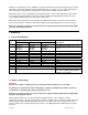
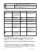
Automatic Shutoff Minutes (if enabled) Beeps Keys Alerts Set Points LCD Contrast Initial Settings Units Mode Disabled 5 Enabled Enabled Momentary 12 lbF Real Time 12.3 Capacity, Resolution & Load Cell Deflection Model Capacity M4-012 lbF 0.12 ozF 2 M4-025 0.25 M4-05 kgF Load Cell Deflection in [mm] Resolution gF 50 N 0.5 4 100 0.5 8 M4-2 2 32 M4-5 5 M4-10 kN mN 500 lbF 0.00005 ozF 0.001 1 1000 0.0001 250 2.5 2500 1 1000 80 2.5 10 160 M4-20 20 M4-50 kgF gF 0.
13 WARRANTY REPAIR POLICY Limited Warranty on Products Any Cooper Instruments product which, under normal operating conditions, proves defective in material or in workmanship within one year of the date of shipment by Cooper will be repaired or replaced free of charge provided that a return material authorization is obtained from Cooper and the defective product is sent, transportation charges prepaid, with notice of the defect, and it is established that the product has been properly installed, maintained,