Series 3 DIGITAL FORCE GAUGES User’s Guide
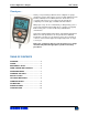
User’s Guide Series 3 Digital Force Gauges Thank you… Thank you for purchasing a Mark-10 Series 3 digital force gauge, designed for tension and compression force testing applications from 0.12 lb to 500 lb (0.5 N to 2,500 N) full scale. The Series 3 is an essential component of a force testing system, typically also comprising a test stand, grips, and data collection software. With proper usage, we are confident that you will get many years of great service with this product.
User’s Guide Series 3 Digital Force Gauges 1 OVERVIEW 1.1 List of included items Qty. 1 1 1 1 1 1 1 1 1 1 1 1 1 M3-012 – M3-20 12-1049 AC1030 / AC1031 / AC1032 08-1026 G1024 G1026 G1025 G1027 G1029 G1028 N/A 09-1165 - Part No.
Series 3 Digital Force Gauges User’s Guide accumulate in the sample during testing. Extra bodily protection should be worn if a destructive failure of a test sample is possible. 6. In certain applications, such as the testing of brittle samples that can shatter, or other applications that could lead to a hazardous situation, it is strongly recommended that a machine guarding system be employed to protect the operator and others in the vicinity from shards or debris. 7.
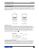
User’s Guide Series 3 Digital Force Gauges 3 MECHANICAL SETUP 3.1 Loading shaft orientation In order to accommodate a variety of testing requirements, the orientation of the loading shaft may be set up in either of the two positions shown below. In order to change the loading shaft orientation, loosen the two captive screws on the back side of the housing, separate the two housing halves, rotate one half 180 degrees, and reassemble.
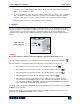
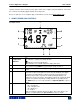
User’s Guide Series 3 Digital Force Gauges operator and others in the vicinity. If using a grip or fixture from a supplier other than Mark-10, ensure that it is constructed of suitably rugged materials and components. Do not use jam nuts or tools to tighten grips or attachments onto the shaft. Finger-tighten only. 4 HOME SCREEN AND CONTROLS 4.1 Home Screen 1 9 2 8 3 7 4 6 No.
User’s Guide Series 3 Digital Force Gauges 6 Mode 7 Battery / AC adapter indicator High / low limit indicators 8 9 Set points The current measurement mode. Abbreviations are as follows: RT – Real Time PC – Peak Compression PT – Peak Tension See Operating Modes section for details about each of these modes Either the AC adapter icon or battery power icon will be shown, depending on power conditions. Refer to the Power section for details. Correspond to the programmed set points.
Series 3 Digital Force Gauges User’s Guide 5 OPERATING MODES Caution! In any operating mode, if the capacity of the instrument has been exceeded by more than 110%, the display will show “OVER” to indicate an overload. A continuous audible tone will be sounded (if beeps are enabled) until the MENU key has been pressed or the load has been reduced to a safe level. Three operating modes are possible with Series 3 gauges. To cycle between the modes, press MODE while in the home screen. 5.
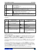
User’s Guide Series 3 Digital Force Gauges DIGITAL FILTERS (1 = Fastest) Current Reading 8 Displayed Reading 1024 Two filters are available: Current Reading – Applies to the peak capture rate of the instrument. Displayed Reading – Applies to the primary reading on the display. Available settings: 1,2,4,8,16,32,64,128,256,512,1024. It is recommended to keep the current reading filter at its lowest value for best performance, and the displayed reading filter at its highest value for best stability.
User’s Guide Series 3 Digital Force Gauges Note: Set point indicators reference the displayed reading, not necessarily the current live load. 9 COMMUNICATIONS Communication with Series 3 force gauges is achieved through the micro USB port located along the left side of the housing, as shown in the illustration in the Power section. Communication is possible only when the gauge is in the main operating screen (i.e. not in a menu or configuration area).
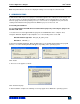
Series 3 Digital Force Gauges User’s Guide Restart the computer before connecting a Mark-10 USB device. 5. After Windows as restarted, plug in the device. The following will occur: Windows 7 Operating Systems – When the Mark-10 USB device has been plugged into a USB port, the driver will automatically be found. When the driver installation is complete, a message will appear as follows: “The MARK-10 USB DEVICE driver is now installed and ready to use”.
Series 3 Digital Force Gauges User’s Guide 7. The next screen appears as follows: Click “Continue Anyway”. 8. The next, and final, screen appears as follows: Click “Finish”. The Mark-10 USB device is now installed and ready to use. The COM port number assigned by Windows may be identified in Device Manager, or in the communication application being used, such as MESURgauge or HyperTerminal. 9.2 Communication Settings To set up communication settings, select USB Settings from the menu.
Series 3 Digital Force Gauges User’s Guide Configure the baud rate and data format as required for the application. Default values are as follows: Baud Rate: Data Format: 9,600 Numeric + units Other communication settings are permanently set to the following: Data Bits: Stop Bits: Parity: 8 1 None Individual data points may be transmitted by pressing DATA. 10 CALIBRATION 10.
User’s Guide Series 3 Digital Force Gauges 3. To escape the Calibration menu at any time, press ESCAPE. The display will appear as follows: CALIBRATION NOT COMPLETE CANCEL EXIT W/O SAVING Selecting “CANCEL” will revert back to the Calibration setup. Selecting “EXIT W/O SAVING” will return to the menu without saving changes. 4. After the number of calibration points has been entered, press ENTER. The display will appear as follows: CALIBRATION OFFSET Place force gauge horizontal THEN PRESS ZERO 5.
Series 3 Digital Force Gauges User’s Guide 7. The display will appear as follows: CALIBRATION COMPRESSION Optionally exercise load cell a few times. THEN PRESS ENTER Optionally exercise the load cell shaft several times (at full scale, if possible), then press ENTER. 8. The display will appear as follows: CALIBRATION COMPRESSION GAIN ADJUST APPLY FULL SCALE LOAD 10.000 LBF +/-20% THEN PRESS ENTER Apply a weight equal to the full scale of the instrument, and then press ENTER. 9.
Series 3 Digital Force Gauges User’s Guide CALIBRATION COMPRESSION COMPLETE REVERSE DIRECTION FOR TENSION Attach necessary weight fixtures. THEN PRESS ENTER Press ENTER. 12. The display will appear as follows: CALIBRATION To invert the display, press the DIRECTION key. THEN PRESS ENTER Reverse the orientation of the load cell shaft by rotating the gauge 180 degrees. Press DIRECTION to invert the display. Then attach weight fixtures.
Series 3 Digital Force Gauges User’s Guide LOAD NOT STABLE PLEASE TRY AGAIN Ensure that the load is not swinging, oscillating, or vibrating in any manner. Then try again. CALIBRATION COMPRESSION LOAD TOO LOW PLEASE TRY AGAIN The calibration weight does not match the set value. CALIBRATION TENSION LOAD TOO CLOSE TO PREVIOUS PLEASE TRY AGAIN The entered calibration point is too close to the previous point. 11 OTHER SETTINGS 11.
Series 3 Digital Force Gauges User’s Guide BACKLIGHT Off On * Auto Set Minutes 1 Select Off for the backlight to be off upon powering on the gauge. Select On for the backlight to be on upon powering on the gauge. Select Auto for the backlight to be on upon powering gauge, but will shut off after a period of inactivity (as defined in the Automatic Shutoff sub-section). The backlight will turn on again when activity resumes.
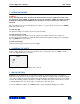
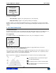
Series 3 Digital Force Gauges User’s Guide INITIAL MODE * Real Time Peak Compression Peak Tension The default value is Real Time. 11.6 Information / Welcome Screen The following screen is displayed at power up and can be accessed at any time by selecting Information from the menu: Digital Force Gauge Series 3 Model No: M3-50 Serial No: 1234567 Version: 1.0 (c) Mark-10 Corp.
User’s Guide Series 3 Digital Force Gauges 12 SPECIFICATIONS 12.1 General Accuracy: Sampling rate: Power: Battery life: ±0.3% of full scale ±1 digit 2,000 Hz AC or rechargeable battery. Low battery indicator appears when battery level is low, and gauge powers off automatically when power reaches critical stage.
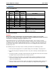
User’s Guide Series 3 Digital Force Gauges 12.3 Capacity, Resolution & Load Cell Deflection Capacity Model lbF kgF Resolution gF N lbF kgF gF N Load Cell Deflection in [mm] 0.005 [0.13] M3-012 0.12 50 0.5 0.0001 0.05 0.0005 M3-025 100 250 1 2.5 0.0002 0.0005 0.1 0.2 0.001 0.002 0.010 [0.25] M3-05 0.25 0.5 M3-2 2 1 10 0.002 0.001 0.01 0.010 [0.25] M3-5 5 2.5 25 0.005 0.002 0.02 0.010 [0.25] M3-10 10 5 50 0.01 0.005 0.05 0.010 [0.25] M3-20 20 10 100 0.
User’s Guide Series 3 Digital Force Gauges NOTES: 21
Series 3 Digital Force Gauges User’s Guide Mark-10 Corporation has been an innovator in the force and torque measurement fields since 1979. We strive to achieve 100% customer satisfaction through excellence in product design, manufacturing and customer support. In addition to our standard line of products we can provide modifications and custom designs for OEM applications. Our engineering team is eager to satisfy any special requirements.