PTT 260 Heavy Duty Digital Pressure Sensor Installation and Maintenance Instructions
WARNING! READ BEFORE INSTALLATION 1. GENERAL: A failure resulting in injury or damage may be caused by excessive overpressure, excessive vibration or pressure pulsation, excessive instrument temperature, corrosion of the pressure containing parts, or other misuse. Consult Cooper Instruments before installing if there are any questions or concerns. 2.
Table of Contents 1. SPECIFICATIONS .................................................................................................................................................. 1 . PRODUCT DIMENSIONS......................................................................................................................................... 2 3. INSTALLATION .....................................................................................................................................................
1. SPECIFICATIONS PERFORMANCE SPECIFICATIONS Humidity: Non-Condensing 0 to 85% RH (Ranges 150 psi and below), 0 to 100% RH (Ranges 300 psi and above) Optional Analog Output (4-20mA): Accuracy ±1.0% FS (Accuracy includes the effects of Linearity, Hysteresis and Repeatability) Response Time: 30msec–10 sec (by user) Output Resolution: ±0.05 FS Analog Scaling: User may configure analog output scaling to any range within –100 to 150% Full Scale of sensor range.
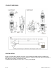
. PRODUCT DIMENSIONS 3. INSTALLATION Install in a location where vibration and shock can be minimized and without direct sunlight on the display and care should be taken to locate the product in compliance with IP65 (150 psi and below) or IP67 (300 psi and above) environmental rating. • Pressure Port Connections ¼ NPT male 1 ½ turns past hand tight.
4. WIRING Cable Color Red Power (+) Black Open Collector Output OUT 1 White Open Collector Output OUT 2 / analog output Green Power (−) Silver Shielded Ground Clear Vent Tube NOTE: Mount M12 connector pins face on with electrical mating cable. Do NOT turn or pull on connector to prevent damage to unit.
CF 197 4 I&M011-10172 Rev A 5/11
5. NOISE PREVENTION Power Supply The pressure display can fluctuate and provide incorrect output if noise is present in the power supply/wires. Care should be taken to keep the PTT 260 power supply wires from high voltage lines and use a power line with a high noise rejection ratio. 6. STORAGE Store in a location in compliance with the environmental rating of the unit and within –20 to +70°C (–4 to 158°F). Avoid direct exposure of the display to Sunlight. 7.
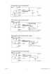
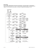
. FUNCTION SETTING MODE Setup Steps Pressing the key greater than 3 seconds will display Function Setting Mode. Scroll through appropriate displays and select feature to change/confirm. LED ring will flash until this menu is exited to the Measurement Mode by holding the key for more than 3 seconds. The setting mode is used to select comparator operation, pressure unit, indication scaling, scaling of analog output and filter time constant.
Filter Setting The PTT 260 is equipped with 5 internal time constant filters. Use of the function is recommended when measuring transient pressure source such that display, comparator output, analog output do not stabilize. The selected time constant filter is reflected on comparator/analog output as well.
Energy-Saving Mode Setting The unit is equipped with automatic display turn-off feature. If user wishes to turn-on the display only when reading the display, or to use the unit mainly for an electrical output reading, this feature can be used. LED Ring Operation Setting LED ring is off (no linkage) LED ring turns Red when comparator 1 is ON, and turn Blue or Green when OFF. LED ring turns Red when comparator 2 is ON, and turn Blue or Green when OFF.
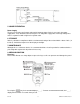
Example 1) Pressure range 0.00~1450 psi (0.0~100.0%F.S.) corresponding to analog output of 4~20mA dc is scaled to pressure range 0.00~1,423 psi (0.0~98.1%F.S.) corresponding to analog output 4~20mA dc. 10. COMPARATOR SWITCH SETTING MODE / LOOP CHECK MODE Setup Steps Pressing the key for less than 3 seconds will display message within the Comparator Setting/Loop Check Mode. Scroll through appropriate displays and select feature to change/confirm.
CF 197 10 I&M011-10172 Rev A 5/11
In “Comparator setting mode”, user can change settings on the comparator outputs provided by the unit. (Two comparator outputs or one for analog output unit are provided). The available selections of this mode varies based on the selections made in Function setting mode and comparator output type selection. For the unit provided with two comparator outputs, settings of each output can be done independently with the exception of the operation mode.
Saving Comparator Setting The comparator settings can be saved to the memory within the unit. The units’ current comparator settings will be saved therefore a comparator setting must be set prior to saving. What data is saved? Comparator(s) Use/No Use setting, comparator operation point (A), dead band (b) and ON/OFF Time delay. What is not saved? Comparator mode and/or output type will not be saved.
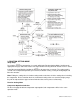
• Operation of Window Comparator Mode 12. OTHER FUNCTIONS Basic Key Operations For setting up in each setting mode, the contents of selection UP/DOWN keys are chosen, respectively. In all setting modes, values are set with the UP/DOWN keys. Use UP key to increase and DOWN key to decrease values. A repeat state occurs in three phases of speed when the UP or DOWN keys are pressed for more than 0.5seconds to increase or decrease numerical value.
displayed as long as press and hold the or keys respectively. When you select this operation, the message is displayed for one second and selected Peak/Bottom value is displayed. Peak and bottom values are reset when you reset power to the unit, or by following procedure. Resetting peak value: While holding the key, press the Resetting bottom value: While holding the key. key, press the key. Key Lock Key operations can be nullified to prevent inadvertent overwriting of setting values.
14.
15. MAINTENANCE Periodic Inspection Depending upon the type of use periodic inspection is recommended at least once a year. Please refer to the following items for periodic inspection. 1. Appearance 2. Display/output check via appropriate pressure standard (1) 3. Display/output check via Loop Check (2) (1) (2) If zero correction is required refer to section 12. Loop check, see section 10. CAUTION • Avoid electrostatic charging. When cleaning this product, please use a soft, damp cloth.