
Owner manual
Model 5i Digital Force / Torque Indicator User’s Guide
19
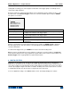
Selection Function when pressing DATA
RS232/USB Output
Outputs data via the serial and USB ports
Mitutoyo Output
Outputs data via Mitutoyo (Digimatic) through the serial port
Memory Storage
Stores a reading to memory (refer to the Memory section for details)
Any combination of the above functions may be selected.
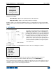
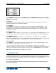
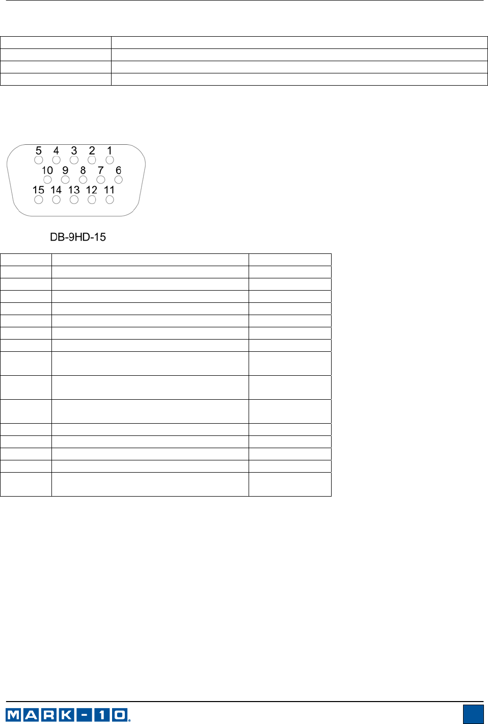
9.7 I/O Connector Pin Diagram (female)
Pin No. Description Input / Output
1 Signal Ground ---
2 Tension/Counter-clockwise Overload Output
3 RS-232 Receive Input
4 RS-232 Transmit Output
5 +12V DC Output
6 Analog Output Output
7 Compression/Clockwise Overload Output
8 Mitutoyo Clock
Output Bit 2
Output
9 Mitutoyo Data
Output Bit 0
Output
10 Mitutoyo Request
Input Bit 3
Input
11 “Under” Set Point Output
12 “Over” Set Point Output
13 “Within” Set Point Output
14 External Trigger Input
15 Mitutoyo Ready
Output Bit 1
Output
9.8 Command Set / Gauge Control Language 2 (GCL2)
The 5i may be controlled by an external device through the RS-232 or USB channel. The following is a list
of supported commands and their explanations. All commands must be terminated with a Carriage Return
character or with a Carriage Return/Line Feed combination. The indicator responses are always
terminated with a Carriage Return/Line Feed.
Request Readings
? Request the displayed reading (dependant on operating mode)
?C Request the current (real time) reading
?PT Request the peak tension reading
?PC Request the peak compression reading
?CW Request the peak clockwise reading
?CCW Request the peak counter-clockwise reading
?ET Request the reading obtained during the External trigger mode
?A Request the average reading obtained during the Average mode