Model 5i DIGITAL FORCE / TORQUE INDICATOR User’s Guide
Model 5i Digital Force / Torque Indicator User’s Guide Thank you… Thank you for purchasing a Mark-10 Model 5i digital force / torque indicator, designed for use with interchangeable remote force and torque sensors. A 5isensor combination can be used with some Mark-10 test stands grips, and data collection software. With proper usage, we are confident that you will get many years of great service with this product.
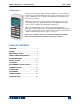
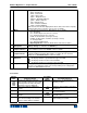
Model 5i Digital Force / Torque Indicator User’s Guide 1 OVERVIEW 1.1 List of included items Qty. 1 1 1 1 1 1 Part No. 12-1049 08-1022 08-1026 09-1165 - Description Carrying Case AC adapter body with US, EU, or UK prong Battery (inside the indicator) Certificate of conformance USB cable Resource CD (USB driver, user’s guides, MESURTM Lite software, MESURTMgauge DEMO software, User’s Guide) 1.
Model 5i Digital Force / Torque Indicator User’s Guide Example 1 Model MR01-100 sensor with Model M5i Indicator MR01-100 ±0.15% of full scale + M5i ±0.1% of full scale ±1 digit = Total ±0.25% of full scale ±1 digit = Total ±0.55% of full scale ±1 digit This translates into a fixed error of up to: 0.25% x 100 lbF = 0.25 lbF + 0.05 lbF = 0.30 lbF Example 2 Model MR50-50Z sensor with Model M3i Indicator MR50-50Z ±0.35% of full scale + M3i ±0.
Model 5i Digital Force / Torque Indicator User’s Guide testing, especially in aforementioned hazardous cases. Extra bodily protection should be worn if a destructive failure of a test sample is possible. 9. In aforementioned hazardous situations, it is strongly recommended that a machine guarding system be employed to protect the operator and others in the vicinity from shards or debris. 10. Sensors have threaded holes or chucks, designed for the mounting of grips, fixtures, or attachments.
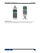
Model 5i Digital Force / Torque Indicator User’s Guide The indicator can be configured to automatically power off following a period of inactivity. Refer to the Other Settings section for details. If battery replacement is necessary, the battery may be accessed by loosening the two captive screws in the rear half of the housing and separating the two halves of the housing. 3 MECHANICAL SETUP 3.
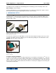
Model 5i Digital Force / Torque Indicator Sensor connector oriented up User’s Guide Sensor connector oriented down 3.3 Mounting to a plate The 5i can be mounted to a plate with four thumb screws fastened into the appropriate holes in the rear half of the housing. Refer to the Dimensions section for detailed hole information and locations.
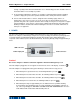
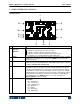
Model 5i Digital Force / Torque Indicator User’s Guide 4 HOME SCREEN AND CONTROLS 4.1 Home Screen 1 11 2 10 3 9 8 4 7 No.
Model 5i Digital Force / Torque Indicator 6 Mode 7 Number of stored data points Battery / AC adapter indicator Automatic data output indicator 8 9 10 High / low limit indicators 11 Set points User’s Guide Torque units: lbFft – Pound-foot lbFin – Pound-inch ozFin – Ounce-inch kgFm – Kilogram-meter kgFmm – Kilogram-millimeter gFcm – Gram-centimeter Nm – Newton-meter Ncm – Newton-centimeter Nmm – Newton-millimeter Note: not all sensor models display all the above units.
Model 5i Digital Force / Torque Indicator UNITS data output, depending on setup. Toggles between measurement units. Turns the LCD backlight on and off. User’s Guide DIRECTION N/A Toggles between tension and compression (or clockwise and counter-clockwise) directions while configuring set points and other menu functions. N/A 4.3 Menu navigation basics Most of the indicator’s various functions and parameters are configured through the main menu. To access the menu press MENU.
Model 5i Digital Force / Torque Indicator User’s Guide 5.4 Average Mode (AVG) Average mode is used to obtain an average load reading over a specified period of time. Applications include measurement of peel force, bearing torque, muscle strength, frictional force, and other tests requiring time-averaged readings. Before the parameters of Average Mode can be configured, it must be enabled. To do so, select Average Mode from the menu, scroll to Enable and press ENTER.
Model 5i Digital Force / Torque Indicator User’s Guide reading with a normally open contact (high to low transition of the trigger signal) or a normally closed contact (low to high transition). Before the parameters of External Trigger Mode can be configured, it must be enabled. To do so, enter the main menu, select External Trigger, scroll to one of the four available options and press ENTER.
Model 5i Digital Force / Torque Indicator User’s Guide DIGITAL FILTERS (1 = Fastest) Current Reading 1 Displayed Reading 1 Two filters are available: Current Reading – Applies to the peak capture rate of the instrument. Displayed Reading – Applies to the primary reading on the display. Available settings: 1,2,4,8,16,32,64,128,256,512,1024. It is recommended to keep the current reading filter at its lowest value for best performance, and the displayed reading filter at its highest value for best stability.
Model 5i Digital Force / Torque Indicator User’s Guide When set points are enabled, the following indicators are shown to the left of the primary reading: – the displayed value is greater than the upper load limit (NO GO HIGH) – the displayed value is between the limits (GO) – the displayed value is less than the lower load limit (NO GO LOW) Set point indicators and outputs reference the displayed reading, not necessarily the current live load.
Model 5i Digital Force / Torque Indicator 0001 0002 0003 0004 D 0005 0006 0007 User’s Guide 8.450 Nm 9.220 Nm 8.445 Nm 8.895 Nm 9.095 Nm 8.990 Nm 9.045 Nm Press ENTER to delete the value. To exit Delete mode, press DELETE again. Any number of readings may be individually deleted, however, all readings may also be cleared simultaneously. Refer to the Clear All Data section for details. 8.2 Statistics Statistical calculations are performed for the saved values.
Model 5i Digital Force / Torque Indicator User’s Guide 1. Insert the Resource CD supplied with the indicator into the CD/DVD drive in the computer. Then, navigate in Windows Explorer or My Computer to one of the following folders on the CD: Windows 2000 through Vista - “Win_2K_XP_S2K3_Vista” Windows 7 - “Windows_7” 2. Execute the installer application “Mark-10USBInstaller.exe” by double-clicking it.
Model 5i Digital Force / Torque Indicator User’s Guide Non-Windows 7 Operating Systems – When the Mark-10 USB device has been plugged into a USB port, the following screen appears: Select “No, not this time”, then click “Next”. 6. The next screen appears as follows: Select “Install the software automatically (Recommended)”, then click “Next”. 7.
Model 5i Digital Force / Torque Indicator User’s Guide Click “Continue Anyway”. 8. The next, and final, screen appears as follows: Click “Finish”. The Mark-10 USB device is now installed and ready to use. The COM port number assigned by Windows may be identified in Device Manager, or in the communication application being used, such as MESURgauge or HyperTerminal. 9.2 Serial / USB To set up RS-232 and USB communication, select Serial/USB Settings from the menu.
Model 5i Digital Force / Torque Indicator User’s Guide 9.3 Automatic Output The indicator has the ability to output data continuously and automatically via RS-232 or USB. To enable automatic output, select Auto Output from the Serial/USB Settings sub-menu. The screen appears as follows: AUTO OUTPUT * Disabled Enabled Outputs per Sec. 10 Select Enabled to activate automatic output. The number of outputs per second can be set to 1, 2, 5, 10, 25, 50, 125, or 250.
Model 5i Digital Force / Torque Indicator Selection RS232/USB Output Mitutoyo Output Memory Storage User’s Guide Function when pressing DATA Outputs data via the serial and USB ports Outputs data via Mitutoyo (Digimatic) through the serial port Stores a reading to memory (refer to the Memory section for details) Any combination of the above functions may be selected. 9.7 I/O Connector Pin Diagram (female) Pin No.
Model 5i Digital Force / Torque Indicator User’s Guide Units (available units depend on the sensor used) LB Switch unit to pound-force OZ Switch unit to ounce-force KG Switch unit to kilogram-force G Switch unit to gram-force N Switch unit to Newton MN Switch unit to milli-Newton KN Switch unit to kilo-Newton LBFT Switch unit to pound-foot LBIN Switch unit to pound-inch OZIN Switch unit to ounce-inch KGM Switch unit to kilogram-meter KGMM Switch unit to kilogram-millimeter GCM Switch unit to gram-centimet
Model 5i Digital Force / Torque Indicator NPOL PM Averaging A AD AM ATn DELn TRFn User’s Guide Mitutoyo output without polarity (absolute value) Print/send data to a Mitutoyo-compatible device Enable Average mode Disable Average mode Select Average mode (if enabled) for primary reading Average time. n=0.1-300.0 seconds Initial delay. n=0.1-300.0 seconds Trigger force.
Model 5i Digital Force / Torque Indicator User’s Guide cells should be used, along with appropriate mounting brackets and fixtures. Caution should be taken while handling such equipment. 10.2 Calibration Procedure In the interests of simplicity and brevity, the following instructions use force terminology only. Such wording is displayed only when a force sensor is being calibrated.
Model 5i Digital Force / Torque Indicator User’s Guide CALIBRATION OFFSET Please wait… CALIBRATION OFFSET CALIBRATION OFFSET Sen.Offset Adj.Passed Ana.Offset Adj.Passed Sen.Offset Adj.Failed Ana.Offset Adj.Failed If failed: 5. The following screen appears after the offsets have been calculated: CALIBRATION COMPRESSION Attach necessary weight fixtures. THEN PRESS ENTER Attach weight fixtures (brackets, hooks, etc), as required. Do not yet attach any weights or apply any calibration loads.
Model 5i Digital Force / Torque Indicator User’s Guide CALIBRATION COMPRESSION ENSURE NO LOAD THEN PRESS ZERO Remove the load applied in Step 8, leave the fixtures in place, then press ZERO. 9. The display will appear as follows: CALIBRATION COMPRESSION APPLY LOAD 1 OF 5 ENTER LOAD: 2.000 LBF THEN PRESS ENTER Use the UP and DOWN keys to adjust the load value as required.
Model 5i Digital Force / Torque Indicator User’s Guide CALIBRATION Units must be gF. PLEASE TRY AGAIN PRESS ENTER Displayed at the start of calibration if a disallowed unit is selected. LOAD NOT STABLE PLEASE TRY AGAIN Ensure that the load is not swinging, oscillating, or vibrating in any manner. Then try again. CALIBRATION COMPRESSION LOAD TOO LOW PLEASE TRY AGAIN The calibration weight does not match the set value.
Model 5i Digital Force / Torque Indicator User’s Guide 11 PASSWORDS Two separate passwords may be set to control access to the Calibration section and to the menu and other keys. To access the passwords setup screen, select Passwords from the menu. The display will appear as follows: PASSWORDS Calibration Menu Key Units Key Mode Key Zero Key Data Key 11.1 Calibration Password Select Calibration from the sub-menu.
Model 5i Digital Force / Torque Indicator User’s Guide Use the UP and DOWN keys to select the correct password, then press ENTER to continue. If the incorrect password has been entered, the display will appear as follows: INCORRECT PASSWORD Reset password Request code: XXXX Press ENTER or ESC To re-enter the password, press ESC to exit to the home screen. Then, access the desired function and enter the password again when prompted. If the password has been misplaced, it can be reset.
Model 5i Digital Force / Torque Indicator User’s Guide BACKLIGHT Off On * Auto Set Minutes 1 Select Off for the backlight to be off upon powering on the indicator. Select On for the backlight to be on upon powering on the indicator. Select Auto for the backlight to be on upon powering indicator, but will shut off after a period of inactivity (as defined in the Automatic Shutoff sub-section). The backlight will turn on again when activity resumes.
Model 5i Digital Force / Torque Indicator User’s Guide This section is used to configure the initial settings upon powering on the indicator. The initial units of measurement and the primary reading measurement mode may be configured. To access these settings, select Initial Settings from the menu. The screen will appear as follows: INITIAL SETTINGS Units LBF Mode Real Time The default unit of measure depends on the sensor series. The default mode is Real Time, regardless of sensor. 12.
Model 5i Digital Force / Torque Indicator User’s Guide 13 SPECIFICATIONS 13.1 General Accuracy: Sampling rate: Power: Battery life: Measurement units: Outputs: Configurable settings: Weight: Included accessories: Warranty: ±0.1% of full scale ±1 digit + sensor 7,000 Hz AC or rechargeable battery. Low battery indicator appears when battery level is low, and indicator powers off automatically when power reaches critical stage.
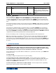
Model 5i Digital Force / Torque Indicator User’s Guide 13.2 Factory Settings Parameter Set points Upper Lower Filters Current Displayed Average mode Initial Delay Trigger Force / Torque Averaging Time (sec.) External Trigger DATA Key Functions RS-232/USB Output Mitutoyo Output Memory Storage Backlight Minutes Serial/USB RS-232 Output Selected USB Output Selected Baud Rate Data Format Auto Output Outputs per Sec.
Model 5i Digital Force / Torque Indicator User’s Guide 13.
Model 5i Digital Force / Torque Indicator User’s Guide NOTES: 33
Model 5i Digital Force / Torque Indicator User’s Guide Mark-10 Corporation has been an innovator in the force and torque measurement fields since 1979. We strive to achieve 100% customer satisfaction through excellence in product design, manufacturing and customer support. In addition to our standard line of products we can provide modifications and custom designs for OEM applications. Our engineering team is eager to satisfy any special requirements.