MasterLink 3000 Wireless Strain Gage Transducer Amplifier and Data Acquisition System USER’S GUIDE www.cooperinstruments.
CONTENTS 1.0 INTRODUCTION ....................................................................................................................1 2.0 SPECIFICATIONS ..................................................................................................................2 2.1 General System Specifications ................................................................................................... 2 2.1 MasterLink 3000 Amplifier Specifications ....................................................
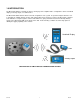
1.0 INTRODUCTION The MasterLink 3000 is a stand-alone wireless strain gage device amplifier that is configurable to either a handheld display, an analog output, or a USB interface. The MasterLink 3000 software allows for the full configuration of the system. A spectrum analyzer allows the user to determine an optimal channel selection and signal health can be monitored. A nine point direct input or applied load calibration is setup through the software and USB device, giving maximum measurement linearity.
2.0 SPECIFICATIONS 2.1 General System Specifications Modulation Method Radio Type Data Type Radio Frequency Power Available Channels QPSK Transceiver (2 way) 250 Kbits/sec 2.4 GHz nominal 1 mW 16 Noise Free Resolution Sample Time <10 ms Sample Time <50 ms Sample Time <100 ms Sample Time <1000 ms Maximum Input Excitation Voltage Range** 15.5 bits 16 bits 17.25 bits 18 bits +/-3.2 mV/V 5 VDC 150 ft **Extended Range available 2.
2.
3.0 SOFTWARE 3.1 System Requirements Supported Operating Systems – Windows Vista, XP, and 7 32 or 64 bit USB Port 3.2 T24 Toolkit Software Installation **It is not necessary to have the MasterLink 3000 amplifier or USB connected to a computer to install the software Insert CD into computer and run setup.exe. Follow the prompts to install the software. 3.
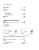
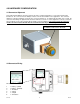
4.0 HARDWARE CONFIGURATION 4.1 Connector Alignment As the MasterLink 3000 has been developed to provide a compact integration to connectorized strain gage transducers, the connector has the ability to rotate to a desired orientation for the application. The connector adapter is a pipe thread which screws into the connector plate block. To maintain the IP rating of the system, the connector must always be tightened into the block and not loosened.
5.0 CONFIGURATION AND CALIBRATION VIA TOOLKIT SOFTWARE **This section is only necessary for changing the default operation characteristics of the MasterLink 3000 or for calibrating a strain gage transducer to a MasterLink 3000 and linking to various data display units (DDU). If a system has been purchased, the applicable DDU's have been setup to the MasterLink 3000 amplifier. The MasterLink 3000 USB unit must be used for calibration of a strain gage transducer.
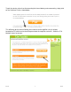
To pair the device, rather than disconnecting the internal battery and reconnecting, simply click on the "click here" link as shown below This will bring up the screen allowing you to connect to the amplifier using its unique hexadecimal ID, which can be found engraved onto the amplifier enclosure.
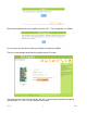
Enter the hexadecimal ID of the amplifier and click "OK". The next prompt is as follows It is not necessary to enter the data tag, therefore it can be left at 0000. The next screen brought up will be the amplifier device ID screen The default name is the S/N of the device, but this is something that could be changed to something like "LC-Tank 1" at the customer's discretion.
5.2 Utilizing the Toolkit Software Calibration of device from Calibration Certificate In some circumstances it may not be possible to apply inputs in which case the calibration can be entered manually from the calibration table or certificate for a loadcell without ever having to connect the loadcell. Items you can change: Number of Calibration Points Enter the number of points you wish to calibrate over. In its simplest form you could select two for a linear calibration.
5.2 Utilizing the Toolkit Software Calibration of device with applied loading Here you can calibrate the acquisition module and set a system zero if required. This simple page allows semi-automated calibration where you can apply known inputs to calibrate. This calibration includes linearization and is automatically applied Calibration Process Decide on how many points you will calibrate over. Decide what inputs will be applied (in ascending order) at each point.
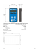
6.0 HANDHELD DEVICE 6.1 Connecting Power Remove the two screws on the rear battery compartment. Insert two alkaline AA batteries. Refit the battery compartment cover. The handheld device is now switched on so should be turned off until the acquisition module is ready. To turn off just hold down the power key until the display shows BUSY then release it. 6.2 Using Toolkit Software to setup Device *Follow steps in section 5.1 to connect to handheld device.
Items you can change: Power On Auto Zero Here you can determine whether the device performs automatic zero when it is powered on. Enter zero to disable this function. If you enter a non-zero value then when the handheld is first turned on it checks the value read from the acquisition module. If this falls within ± of this value then the display will be altered so this reads zero. In its simplest form you could select two for a linear calibration.
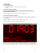
Items you can change: Format & Resolution Here you can define how the values are displayed on the LCD. There are 7 digits available and you can define where the decimal point is shown by entering text where a zero indicates a numeric digit position. When the data is being displayed the number of decimal places you define may be overridden as the display will always show the correct number of integer digits. Example: If you set the format to 000.0000 and the value to display is 1000.
Overload Limit You can enter a limit here above which Overload will be shown on the display instead of the actual value. Enter zero to disable this feature.This can be turned on or off and will suppress leading zeroes when on. Timeout Enter the timeout in seconds. This sets the time allowed without any data arriving from the viewed module before all dashes are displayed on the LCD. Should be at least 3 times the interval between the data being transmitted by the acquisition module. 6.
7.0 ANALOG OUTPUT 7.1 Connecting Power You will need to connect a power supply to the device for it to operate and to enable configuration using a base station and the appropriate toolkit software. Power is supplied via the screw terminals and can be in the range of 9 to 36V DC. 7.
7.3 Using Toolkit Software to setup Device *Follow steps in section 5.1 to connect to analog amplifier. Items you can change: Input In Minimum CF 187 Enter the input value that should result in the minimum output. The minimum output depends on the Current Selected Output which is determined by the SW2 DIP switch settings.
In maximum Enter the input value that should result in the maximum output. The maximum output depends on the Current Selected Output which is determined by the SW2 DIP switch settings. Input value This shows the currently supplied value to the device. An active acquisition module must be in place to view this value. Here you can set the action to take when certain errors occur.
Items you can change: Timeout Enter the timeout in milliseconds for the input to timeout. If a new Data Provider packet does not arrive within this time the Timeout Action will trigger. Generally this timeout should be set to at least three times the acquisition module transmission rate. Timeout Action Select the action to take place when a timeout occurs. i.e. when communications (for more than the duration of the Timeout value) is lost with the acquisition module.
WARRANTY REPAIR POLICY Limited Warranty On Products Any Cooper Instruments product which, under normal operating conditions, proves defective in material or in workmanship within one year of the date of shipment by Cooper will be repaired or replaced free of charge provided that a return material authorization is obtained from Cooper and the defective product is sent, transportation charges prepaid, with notice of the defect, and it is established that the product has been properly installed, maintained, an